Method and device for controlling auto focusing of a video camera by tracking a region-of-interest

a video camera and auto focusing technology, applied in the field of video camera auto focusing control by tracking a region of interest, can solve the problems of inability to apply methods in the general case of target identification, difficulty in detecting the reflected wave of the camera, and inability to automatically identify the target, etc., to achieve low computational complexity, simple shape matching procedure, and low computational complexity

a video camera and auto focusing technology, applied in the field of video camera auto focusing control by tracking a region of interest, can solve the problems of inability to apply methods in the general case of target identification, difficulty in detecting the reflected wave of the camera, and inability to automatically identify the target, etc., to achieve low computational complexity, simple shape matching procedure, and low computational complexity

US8089515B2Active Publication Date: 2012-01-03WSOU INVESTMENTS LLC

Image

  • Method and device for controlling auto focusing of a video camera by tracking a region-of-interest
  • Method and device for controlling auto focusing of a video camera by tracking a region-of-interest
  • Method and device for controlling auto focusing of a video camera by tracking a region-of-interest

Examples


Embodiment Construction

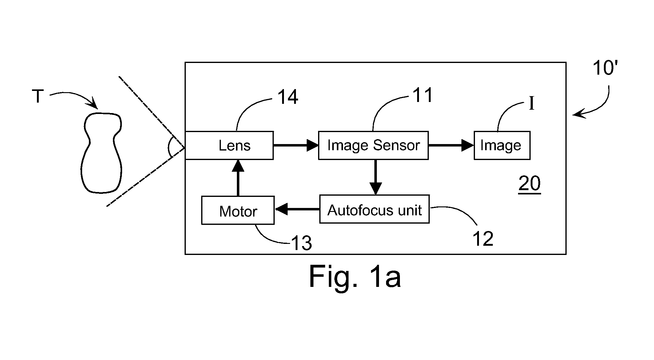
[0048]Nowadays, many electronic devices 10 include camera means 11. Besides digital video cameras, examples of such devices include mobile stations, PDA (Personal Digital Assistant) devices, and similar ‘smart communicators’ and also surveillance cameras. In this connection, the concept ‘electronic device’ can be understood very widely. For example, it can be a device, which is equipped, or which can be equipped with a digital video imaging capability. In the following, the invention is described in connection with a mobile station 10, by way of example.

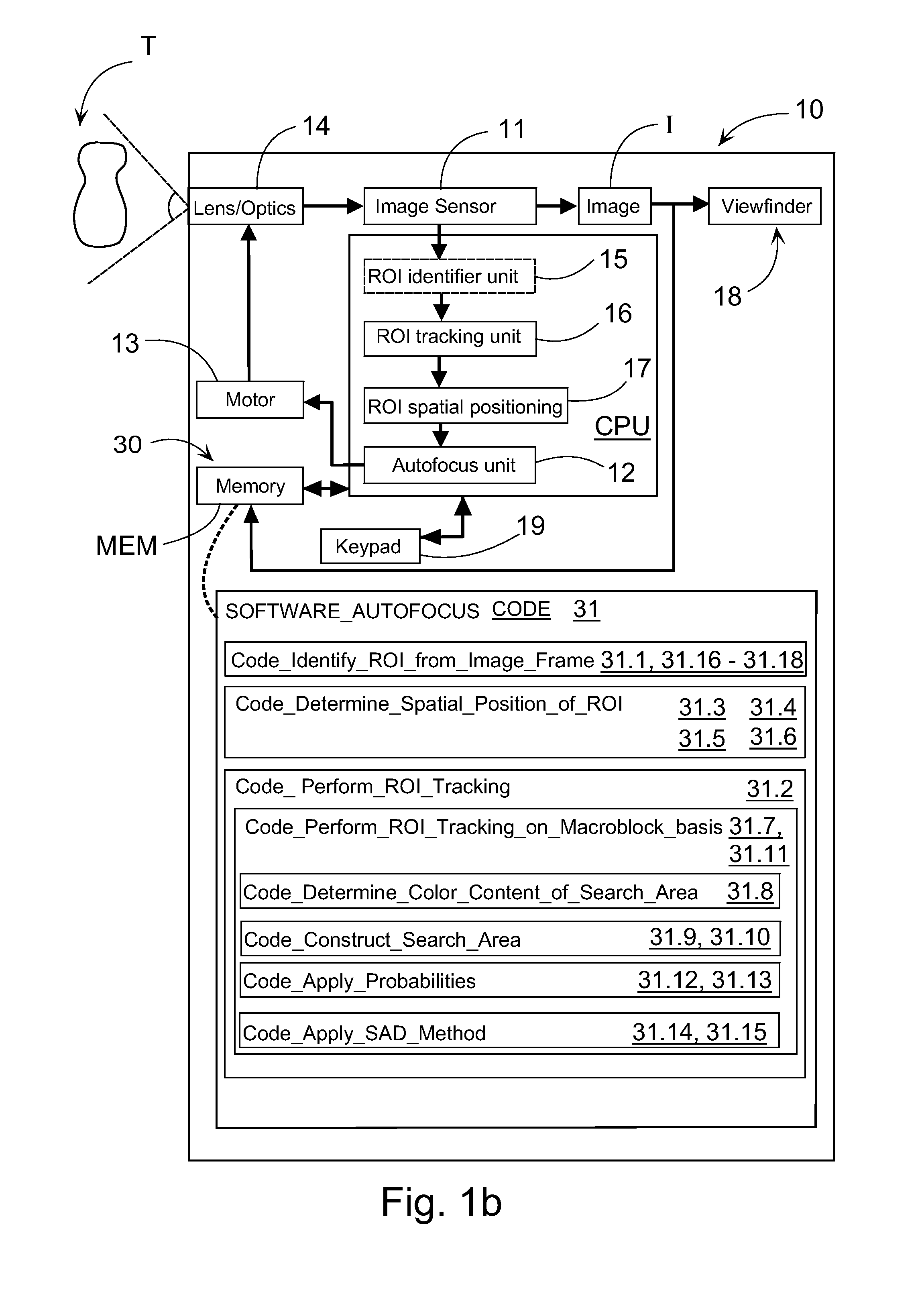
[0049]FIG. 1b shows a rough schematic example of the functionalities in a device 10, in as much as they relate to the invention. The camera means of the device 10 can include the functional components or sub-modules 11-14, which are, as such known, shown in FIG. 1b and already described in connection with FIG. 1a in the prior art section. These modules 11-14 form a loop architecture, which is performed continuously in connection with...


PUM


Abstract

The invention concerns an electronic device equipped with a video imaging process capability, which device includes a camera unit arranged to produce image frames from an imaging view which includes a region-of-interest ROI, an adjustable optics arranged in connection with the camera unit in order to focus the ROI on the camera unit, an identifier unit in order to identify a ROI from the image frame, a tracking unit in order to track the ROI from the image frames during the video imaging process and an auto-focus unit arranged to analyze the ROI on the basis of the tracking results provided by the tracking unit in order to adjust the optics. The device is arranged to determine the spatial position of the ROI in the produced image frame without any estimation measures.

Description

FIELD OF THE INVENTION[0001]The present invention relates to an electronic device equipped with a video imaging process capability, which device includes[0002]a camera unit arranged to produce image frames from an imaging view which includes a region-of-interest ROI,[0003]an adjustable optics arranged in connection with the camera unit in order to focus the ROI on the camera unit,[0004]an identifier unit in order to identify a ROI from the image frame,[0005]a tracking unit in order to track the ROI from the image frames during the video imaging process and[0006]an auto-focus unit arranged to analyze the ROI on the basis of the tracking results provided by the tracking unit in order to adjust the optics.[0007]In addition, the invention also relates to a method and a corresponding program product.BACKGROUND OF THE INVENTION[0008]In FIG. 1a has been presented a prior art example of the generic architecture of a passive auto-focus system arranged in connection with a digital imaging sys...

Claims


Application Information

Patent Timeline
03 Jan 2012
Publication
US8089515B2
IPC
H04N5/225; G02B7/28; G02B7/36; G03B13/36; G03B30/00
CPC
G03B13/36; G06T7/20; H04N5/23212; H04N23/673
Inventors
CHEBIL, FEHMI; BEN HADJ MILED, MOHAMED KHAMES