Apparatus for hot fusion of fusion-reactive gases

a technology of fusion-reactive gases and apparatus, which is applied in the direction of nuclear reactors, nuclear engineering, greenhouse gas reduction, etc., can solve the problems of inherently inefficient operation, and inability to achieve the effect of high temperature and momentarily high pressur

Active Publication Date: 2012-01-03
DELUZE JAMES ROBERT
View PDF12 Cites 18 Cited by
  • Summary
  • Abstract
  • Description
  • Claims
  • Application Information

AI Technical Summary

Benefits of technology

[0016]Envelopment of the reactor insulating and cooling medium within a thermally insulated container provides for the outward transport of energy radiations with restriction of inward passage of heat energy. This reduces the thermal load of the reactor and the contained insulating and cooling medium from reabsorption of heat produced within the absorber medium.

Problems solved by technology

High temperatures and momentarily high pressures do occur during the operation of this device.
It became obvious that such attempts are futile here on Earth.
The conditions on Earth make such operation inherently inefficient.
This device does not use actual sonoluminescence, imploding bubbles, or cavitation phenomenon.
The asymmetry of the resultant electric field did not sufficiently hamper the device's function as an electric light.
However, such asymmetry of the electric field would lead to inadequate focus of the ions onto the central target electrode for fusion reactions to occur.
Such arcing is visually pleasing in a lighted lamp, but would prevent the device from producing reliable fusion reactions.
This sleeve would further interfere with the electric field symmetry rendering the device in operable for fusion reactions.
Such devices work, but work only as one shot devices.
The presence of a physical target limits power levels to those levels within which the target will survive.

Method used


Image

  • Apparatus for hot fusion of fusion-reactive gases
  • Apparatus for hot fusion of fusion-reactive gases
  • Apparatus for hot fusion of fusion-reactive gases

Examples


Embodiment Construction

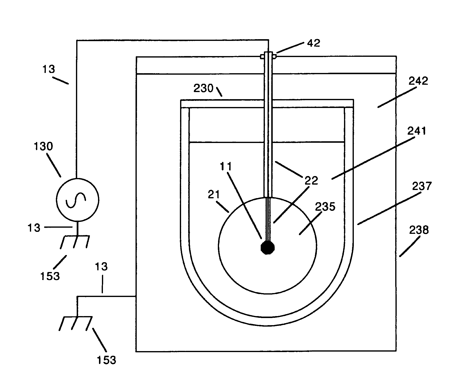
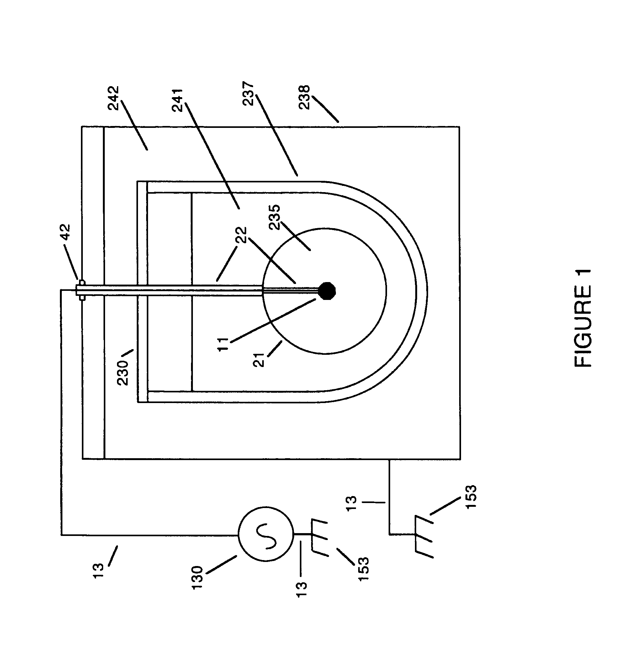
[0025]FIG. 1 shows a non conducting spherical reactor envelope 21 having an internal insulated stalk 22 extending centrally from which a spherical target electrode 11 is located centrally, coaxially, and fixedly within envelope 21. An open space is defined between spherical electrode 11 and the inner surface of spherical envelope 21. This defined space contains rarefied Deuterium gas 235. This gas 235 may also consist of Tritium, or mixture of Deuterium and Tritium, or any other fusion reactive gases. This space also provides a location for the generation of an alternating electric field.

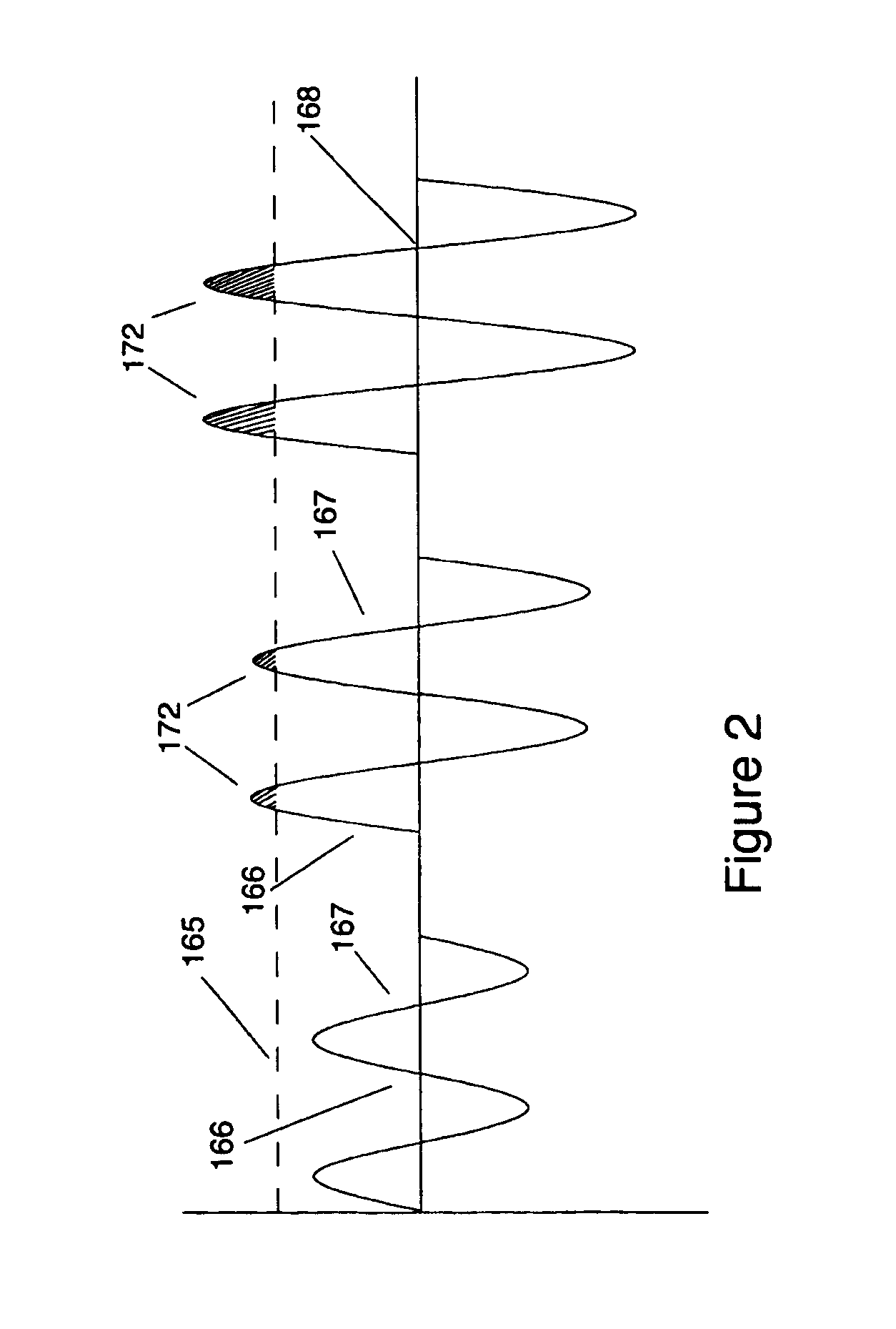
[0026]This alternating electric field provides for the ionization of gases contained therein. It also provides for the alternately radial inward acceleration and the alternately radial outward acceleration of ionized gases contained therein. The collapsing of ionized gases provides for ions impacting the spherical target, for the impact of ions with one another, and for such impacts to occur at fusi...


PUM


Abstract

A generally spherical sealed reactor vessel defining a volume. A target sphere shaped electrode 11 is centered within a nonconductive reactor vessel 21. The target sphere is insulated from and fixedly centered within the nonconductive reactor vessel by an insulated stalk 22. This vessel is suspended in an insulating and cooling medium 241 composed of transformer oil. Deuterium gas 235 is released into and contained within the volume at a predetermined pressure. A source of high voltage, high frequency potential 130 is connected to the target electrode by an electrical connection 13. The other terminal of the high voltage, high frequency potential source is connected to Earth ground 153. The applied alternating electrical potential creates an alternating electrical field within the reaction chamber. This an oscillating electric field is formed within the enclosed space of nonconductive reactor vessel 21, extending between target electrode 11 and heat absorbent container 238. This electric field is of sufficient intensity to provide for the ionization of gases contained therein. It also provides for the alternately radial outward acceleration and the alternately radial inward acceleration of the contained ionized gases. The collapsing of ionized gases provides for ions impacting the spherical target, and for the impact of ions with one another. The intensity of the electric field is sufficient that such impacts occur at fusion reactive velocities.

Description

CROSS-REFERENCE TO RELATED APPLICATIONS[0001]This application claims the benefit of Provisional Patent Application Ser. No. 60 / 311,453, filed 2001 Aug. 8 by the present inventor.FEDERALLY SPONSORED RESEARCH[0002]Not applicable.SEQUENCE LISTING OR PROGRAM[0003]Not applicable.BACKGROUND[0004]1. Field of Invention[0005]This invention relates to hot nuclear fusion reactions of heavy and light Hydrogen and other fusion reactive gases for the production and recovery of energy.[0006]2. Description of Prior Art[0007]Electric illumination supplies a basic need of modern society. To this end, inventors created several types of electric lights. U.S. Pat. No. 514,170 to Tesla (1894), which is hereby incorporated by reference, discloses a partially evacuated, bulb shaped glass enclosure with a central target. This central electrode is attached by a stalk containing an electrically conductive element. The conducting element is attached to a source of high voltage, high frequency electrical potent...

Claims


Application Information

Patent Timeline
Patent Type & Authority Patents(United States)
IPC IPC(8): G21B1/00
CPCG21B3/006Y02E30/10
Inventor DELUZE, JAMES ROBERT
Owner DELUZE JAMES ROBERT
Why Eureka
Try Eureka