
Manufacturing method for liquid discharge head substrate

a manufacturing method and liquid discharge technology, applied in the direction of recording equipment, recording information storage, instruments, etc., can solve the problems of long etching period, increased ink supply port opening size of the reverse of the silicon substrate, and difficulty in downsizing the head, so as to achieve stably and efficiently manufacturing the ink jet recording head substrate and prevent the effect of widening the supply por

Inactive Publication Date: 2012-01-10
CANON KK
View PDF13 Cites 11 Cited by
  • Summary
  • Abstract
  • Description
  • Claims
  • Application Information

AI Technical Summary

Benefits of technology

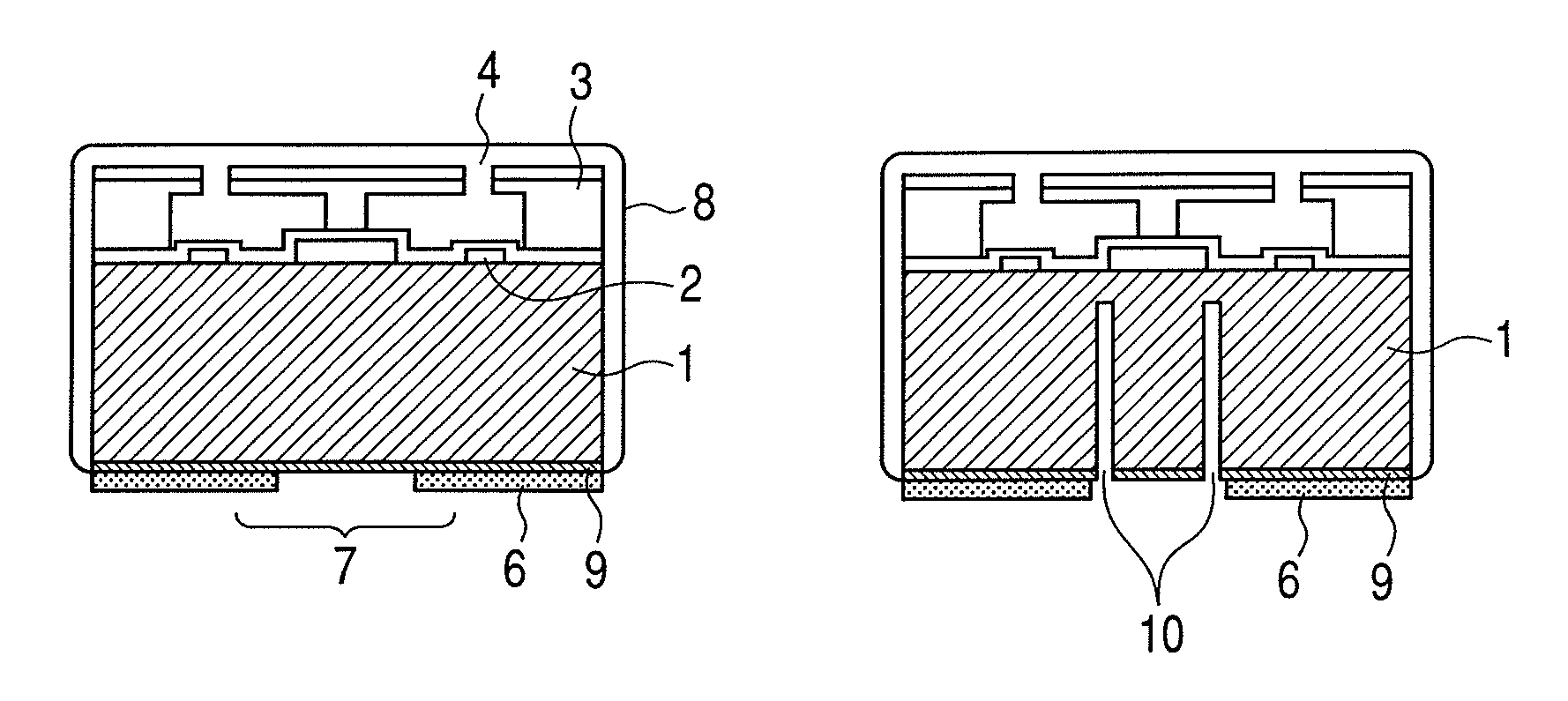
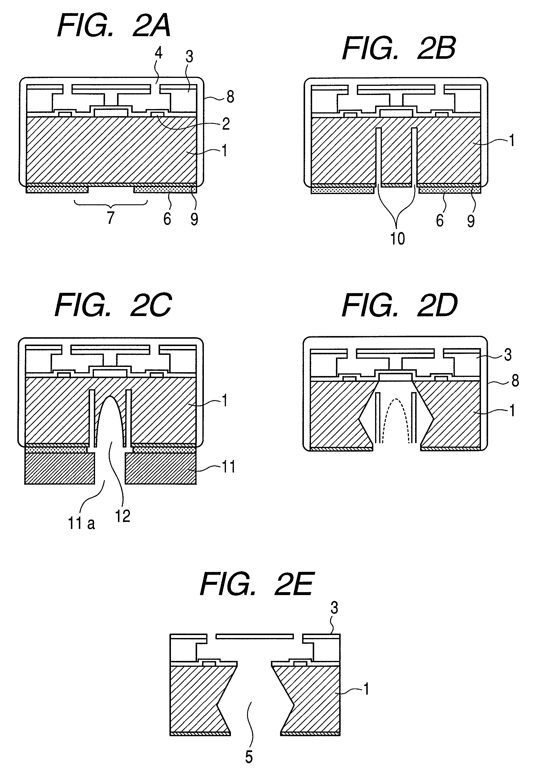
The present invention provides a method for manufacturing an ink jet recording head substrate that prevents widening of the supply port. This allows for stable and efficient production of the substrate. The method includes steps of providing a silicon substrate, adding a mask layer with an opening that matches the supply port, creating a groove in the silicon substrate, removing silicon from the groove using sandblasting, and then performing an anisotropic etching of the silicon substrate to form the supply port. The invention prevents widening of the supply port, resulting in a more stable and efficient ink jet recording head substrate.

Problems solved by technology

However, since the method disclosed in U.S. Pat. No. 6,143,190 employs anisotropic wet etching for the formation of an ink supply port, a long etching period is required.
In addition, according to this method, since the opening size is determined in accordance with the {111} plane along the silicon crystal axis, the opening size of the ink supply port on the reverse of the silicon substrate is increased, and downsizing of the head is therefore difficult.
To do this, the amount of material removed by dry etching must be increased; however, since an extended period is required for dry etching, in such a case, deterioration of the production efficiency may occur.

Method used


Image

  • Manufacturing method for liquid discharge head substrate
  • Manufacturing method for liquid discharge head substrate
  • Manufacturing method for liquid discharge head substrate

Examples


Embodiment Construction

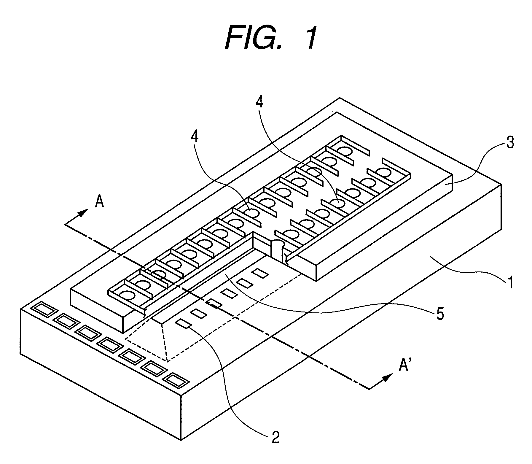
[0017]One embodiment of the present invention will now be described while referring to accompanying drawings. In the following description, the same reference numbers are employed in the drawings for arrangements having the same function, and no further description will be given. Furthermore, in the following description, an ink jet recording head substrate that can be mounted in an ink jet recording head is employed as an example liquid discharge head substrate used for a liquid discharge head. However, the liquid discharge head substrate of the present invention is not limited to such a use, and can also be applied for a DNA chip and a liquid discharge head used for manufacturing display devices.

[0018]As will be described below, according to this invention, a method for manufacturing an ink jet recording head substrate is characterized by the processing performed to form an ink supply port.

[0019]First, a groove formation process is performed using a laser by superimposing non-perf...


PUM

PropertyMeasurementUnit
widthaaaaaaaaaa
average grain diameteraaaaaaaaaa
pressureaaaaaaaaaa

Abstract

A manufacturing method, for a liquid discharge head that includes a silicon substrate in which a supply port is formed for supplying a liquid, includes the steps of providing the silicon substrate, a mask layer provided with an opening that corresponds to the supply port being provided on one face of the silicon substrate; forming a groove in the silicon substrate along the shape of the opening in the mask layer; removing, via sandblasting, silicon of the silicon substrate inward of the groove in the silicon substrate; and performing, from the one face, anisotropic etching of the silicon substrate that has been sandblasted, and forming the supply port.

Description

BACKGROUND OF THE INVENTION[0001]1. Field of the Invention[0002]The present invention relates to a method for manufacturing a liquid discharge head substrate.[0003]2. Description of the Related Art[0004]An ink jet recording head that has been adapted and used as a well known liquid discharge head has an arrangement much like that illustrated in FIG. 3. As shown in FIG. 3, a through hole is opened from the reverse to the obverse face of a silicon substrate 101 where heaters 102 are mounted on the obverse face, and serves as an ink supply port 113, via which ink is supplied from the reverse to the obverse side of the silicon substrate 101.[0005]A method for manufacturing such an ink jet recording head is disclosed in U.S. Pat. No. 6,143,190. The use of this manufacturing method is proposed to prevent discrepancies in the opening diameter of an ink supply port 113, a through hole, and includes the following processes: 1) a process for forming on the obverse face of a silicon substrate,...

Claims


Application Information

Patent Timeline
Patent Type & Authority Patents(United States)
IPC IPC(8): B21D53/76B23P17/00
CPCB41J2/1603B41J2/1629B41J2/1631B41J2/1634B41J2/1635B41J2/1645B41J2/1632Y10T29/49401
Inventor IBE, SATOSHIKOMURO, HIROKAZUHATSUI, TAKUYAASAI, KAZUHIROOTAKA, SHIMPEIKOMIYAMA, HIROTOKISHIMOTO, KEISUKE
Owner CANON KK
Learn More