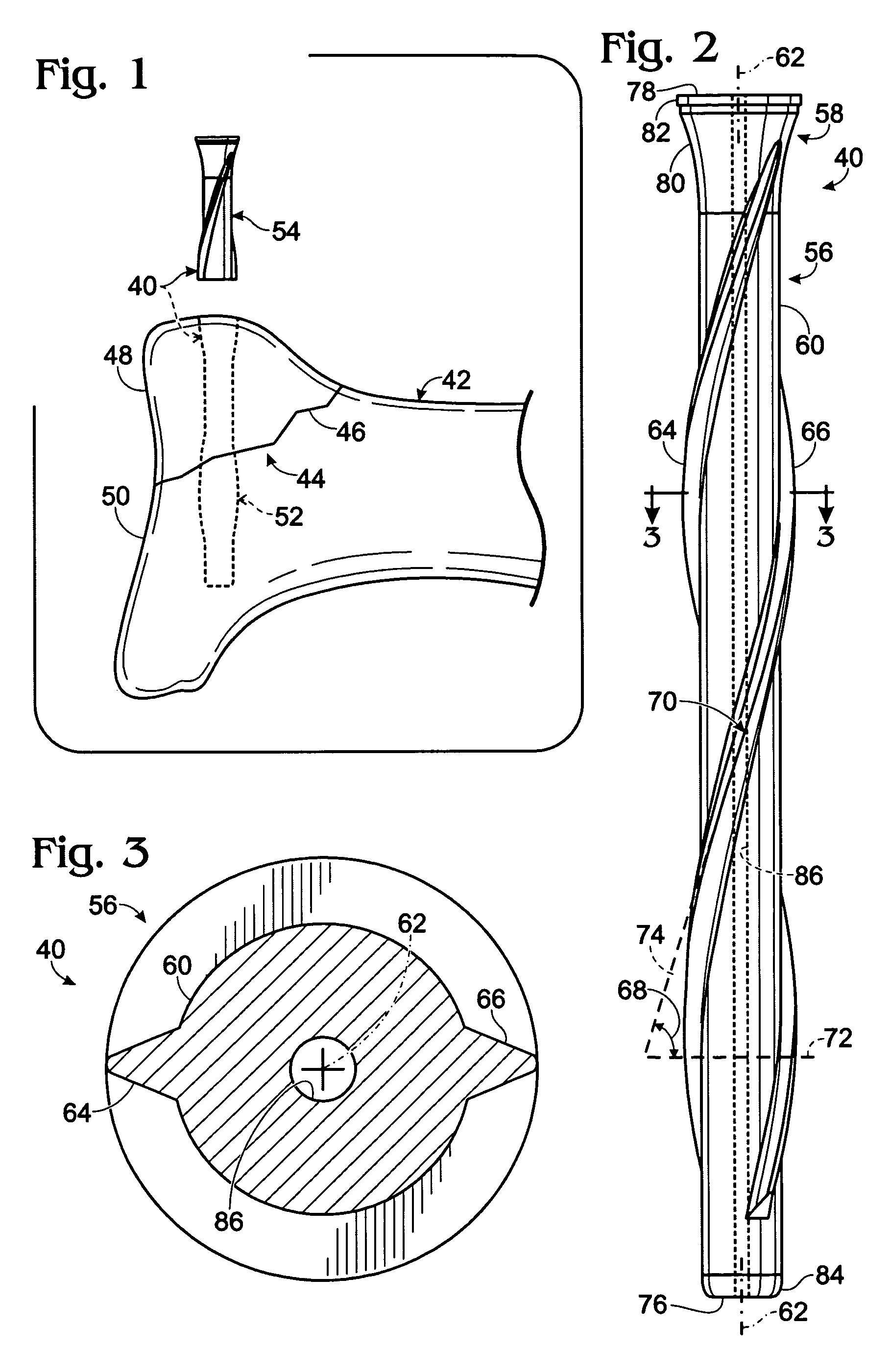
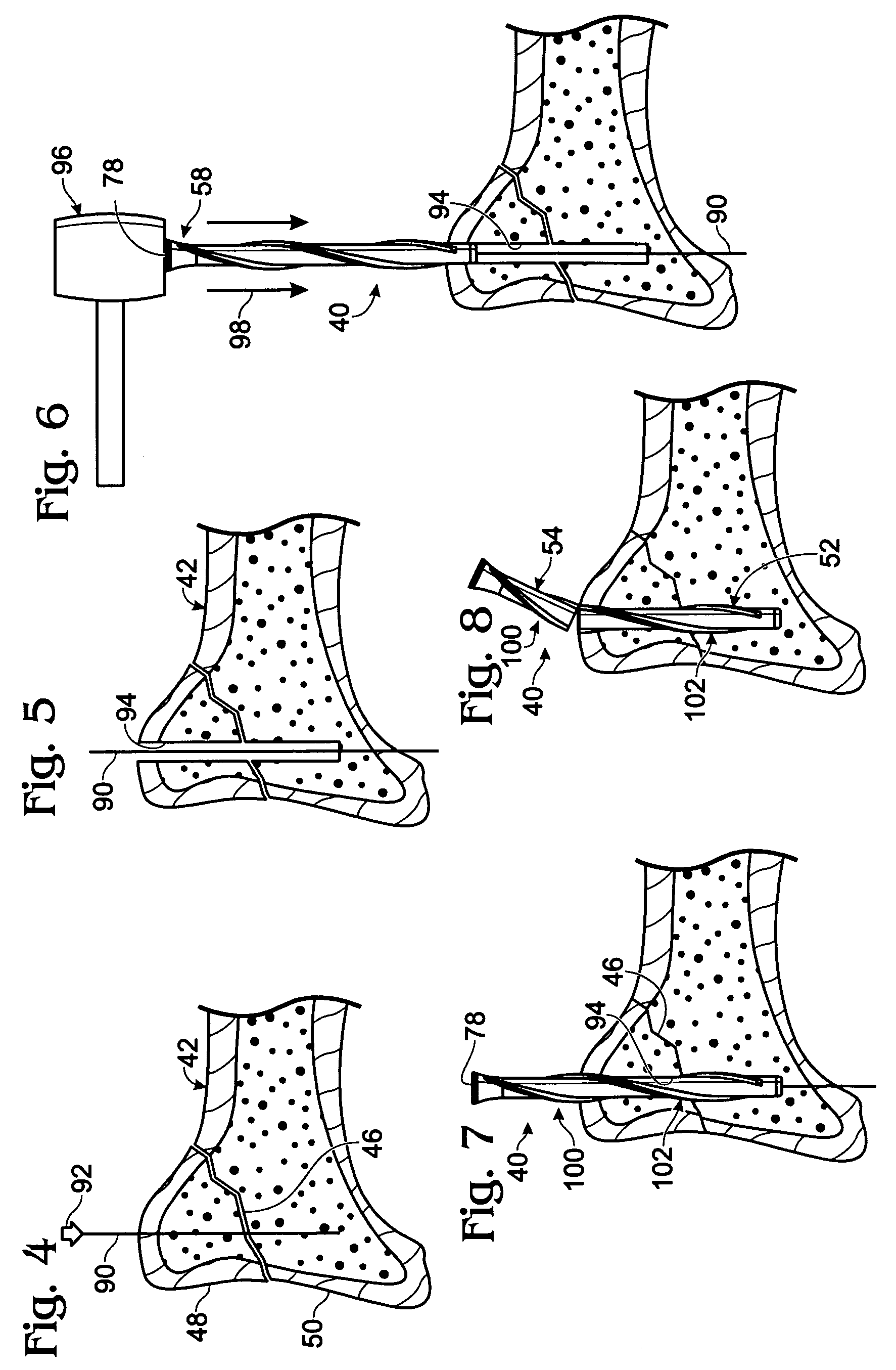
Bone nail
a bone nail and nail technology, applied in the field of bone nails, can solve the problems of many orthopedic applications where bone pins may be inferior to bone screws, and many cases where bone pins may not be suitable for us
- Summary
- Abstract
- Description
- Claims
- Application Information
AI Technical Summary
Benefits of technology
Problems solved by technology
Method used
Image
Examples
example 1
Exemplary Method of Nail Installation
[0068]This example describes another exemplary method of nail installation; see FIGS. 9 and 10. Any suitable aspects of the method described in this example may be combined with aspects of the method described elsewhere herein, such as above in Sections I and VI.
[0069]FIG. 9 shows a configuration of fractured bone 42 produced as an exemplary bone nail 104 is being driven into the bone. Bone nail 104 may be shorter than bone nail 40 (see Section I) and may include any of the features disclosed elsewhere in the present disclosure, such as a tapered head 106 connected to a body 108. The bone nail also has a trailing boundary that forms a trailing end 110.
[0070]The bone nail may be struck directly with an impact tool 96 or axial force may be transferred from the impact tool to the nail via a force-transfer tool 112, such as a punch tool, which may be described as a plunger. The force-transfer tool may be disposed in contact with the nail when struck ...
example 2
Exemplary Bone Nail with Varying Pitch
[0073]This example describes an exemplary tapered bone nail 130 with helical ridges of varying pitch; see FIGS. 11-13.
[0074]FIG. 11 shows a side view of bone nail 130. The bone nail may be divided conceptually into a leading portion 132 and a trailing portion 134 arranged axially along the bone nail. The bone nail may include a head 136 extending from a body 138. The body may include a shaft 140 and at least one or two or more helical ridges 142, 144 formed on the shaft. Each helical ridge may have any of the properties of helical ridges described in the present disclosure. Furthermore, each helical ridge may have a varying pitch. In particular, each ridge may have a relative increase in pitch toward a leading end 146 of the nail, and a relative decrease in pitch toward a trailing end 148 of the nail. Accordingly, a pitch of each helical ridge in leading portion 132 may be greater than the pitch of such helical ridge in trailing portion 134 with...
example 3
Exemplary Bone Nails-Selected Embodiments
[0079]This example describes various exemplary embodiments of axially driven bone nails having a large pitch; see FIGS. 14-19.
[0080]FIG. 14 shows a bone nail 160 including helical ridges 162, 164 of large pitch and discontinuous structure. Each helical ridge may be divided into two or more spaced ridge segments 166 that extend along the same helical path. The ridge segments (and the ridges in other embodiments) may be disposed such that each of their opposing ends is spaced from both ends of the nail.
[0081]FIG. 15 shows a bone nail 180 that may be installed without pre-forming a hole in bone. Nail 180 may have any of the features described in the present disclosure including helical ridges of large pitch. However, nail 180 may be more slender, solid instead of cannulated, and more pointed to provide a pointed tip 182 for forming a path in target tissue. In some cases, nail 180 may be suitable for use in tissue that is softer than bone, such a...
PUM
 Abstract
Description
Claims
Application Information
 - R&D
- Intellectual Property
- Life Sciences
- Materials
- Tech Scout
- Unparalleled Data Quality
- Higher Quality Content
- 60% Fewer Hallucinations
Browse by: Latest US Patents, China's latest patents, Technical Efficacy Thesaurus, Application Domain, Technology Topic, Popular Technical Reports.
© 2025 PatSnap. All rights reserved.Legal|Privacy policy|Modern Slavery Act Transparency Statement|Sitemap|About US| Contact US: help@patsnap.com


