AI technical title is built by PatSnap AI team. It summarizes the technical point description of the patent document.
a source and x-ray technology, applied in the field of x-ray sources, can solve problems such as reducing the target lifetime, and achieve the effects of good thermal matching, low distortion, and high thermal conductivity
Active Publication Date: 2012-01-10
RAPISCAN SYST INC (US)
View PDF120 Cites 60 Cited by
Summary
Abstract
Description
Claims
Application Information
AI Technical Summary
This helps you quickly interpret patents by identifying the three key elements:
Problems solved by technology
Method used
Benefits of technology
Benefits of technology
[0009]Accordingly, the anode may be formed in two parts, and the X-ray aperture can conveniently be defined between the two parts. This enables simple manufacture of the anode. The two parts are preferably arranged to be held at a common electrical potential.
[0017]In one embodiment, the anode segments are formed from a material with a high thermal conductivity such as copper. The rigid backbone may preferably be formed from stainless steel. The excellent thermal matching of copper and stainless steel means that large anode segments may be fabricated with little distortion under thermal cycling and with good mechanical stability.
[0018]The plurality of anode segments may be bolted onto the rigid backbone. Alternatively, the rigid backbone may be crimped into the anode segments using a mechanical press. Crimping reduces the number of mechanical processes required and removes the need for bolts, which introduce the risk of gas being trapped at the base of the bolts.
[0019]The integral cooling channel may extend along the length of the backbone and may either be cut into the anode segments or into the backbone. Alternatively, the channel may be formed from aligned grooves cut into both the anode segments and the backbone. A cooling tube may extend along the cooling channel and may contain cooling fluid. Preferably, the tube is an annealed copper tube. The cooling channel may have a square or rectangular cross section or, alternatively, may have a semi-circular or substantially circular cross section. A rounded cooling channel allows better contact between the cooling tube and the anode and therefore provides more efficient cooling.
Problems solved by technology
This heat can reduce the target lifetime and it is therefore common to cool the anode.
Method used
Image
Click on the blue label to locate the original text in one second.
Reading with bidirectional positioning of images and text.
Examples
Embodiment Construction
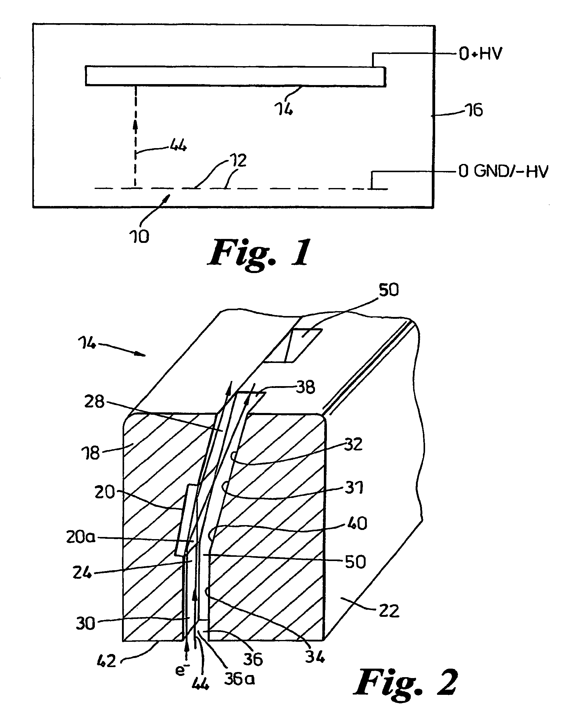
[0039]Referring to FIG. 1, an X-ray tube according to the invention comprises a multi-element electron source 10 comprising a number of elements 12 each arranged to produce a respective beam of electrons, and a linear anode 14, both enclosed in a tube envelope 16. The electron source elements 12 are held at a high voltage negative electrical potential with respect to the anode.
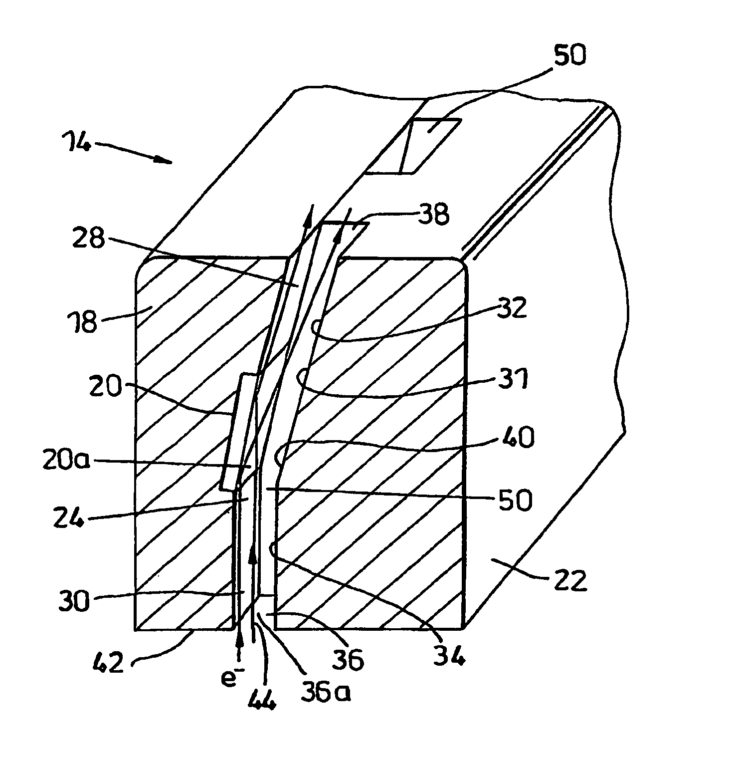
[0040]Referring to FIG. 2, the anode 14 is formed in two parts: a main part 18 which has a target region 20 formed on it, and a collimating part 22, both of which are held at the same positive potential, being electrically connected together. The main part 18 comprises an elongate block having an inner side 24 which is generally concave and made up of the target region 20, an X-ray collimating surface 28, and an electron aperture surface 30. The collimating part 22 extends parallel to the main part 18. The collimating part 22 of the anode is shaped so that its inner side 31 fits against the inner side 24 of th...
PUM
Abstract
The present invention is directed to an anode for an X-ray tube. The X-ray tube has an electron aperture through which electrons emitted from an electron source travel subject to substantially no electrical field and a target in a non-parallel relationship to the electron aperture and arranged to produce X-rays when electrons are incident upon a first side of the target, wherein the target further comprises a cooling channel located on a second side of the target. The cooling channel comprises a conduit having coolant contained therein. The coolant is at least one of water, oil, or refrigerant.
Description
CROSS-REFERENCE[0001]The present invention is a continuation-in-part of U.S. patent application Ser. No. 12 / 364,067, filed on Feb. 2, 2009, which is a continuation of U.S. patent application Ser. No. 12 / 033,035, filed on Feb. 19, 2008 now U.S. Pat. No. 7,505,563, which is a continuation of U.S. patent application Ser. No. 10 / 554,569, filed on Oct. 25, 2005 now U.S. Pat. No. 7,349,525, which is a national stage application of PCT / GB2004 / 001732, filed on Apr. 23, 2004 and which, in turn, relies on Great Britain Patent Application Number 0309374.7, filed on Apr. 25, 2003, for priority.[0002]The present invention also relies on Great Britain Patent Application Number 0812864.7, filed on Jul. 15, 2008, for priority.[0003]All of the aforementioned applications are incorporated herein by reference.FIELD OF THE INVENTION[0004]The present invention relates generally to the field of X-ray sources and more specifically to the design of anodes for X-ray sources along with cooling of the anodes ...
Claims
Application Information
Patent Timeline
Application Date:The date an application was filed.
Publication Date:The date a patent or application was officially published.
First Publication Date:The earliest publication date of a patent with the same application number.
Issue Date:Publication date of the patent grant document.
PCT Entry Date:The Entry date of PCT National Phase.
Estimated Expiry Date:The statutory expiry date of a patent right according to the Patent Law, and it is the longest term of protection that the patent right can achieve without the termination of the patent right due to other reasons(Term extension factor has been taken into account ).
Invalid Date:Actual expiry date is based on effective date or publication date of legal transaction data of invalid patent.

