
Balcony structure

a balcony and structure technology, applied in the direction of screws, threaded fasteners, bolts, etc., to achieve the effect of less vertical deflection, greater load carrying capacity, and less vertical deflection

Active Publication Date: 2012-01-17
NUCOR CORP
View PDF56 Cites 26 Cited by
  • Summary
  • Abstract
  • Description
  • Claims
  • Application Information

AI Technical Summary

Benefits of technology

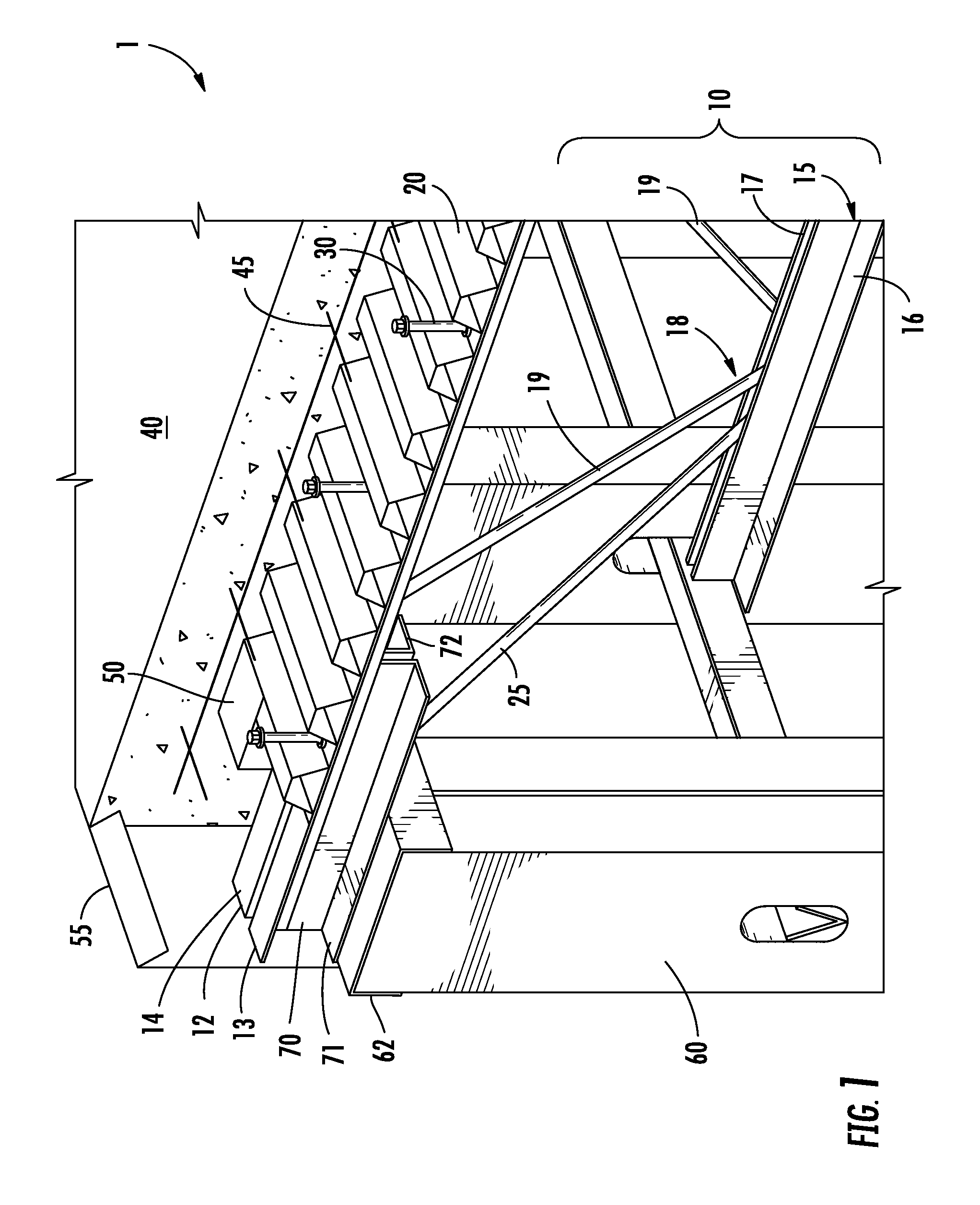
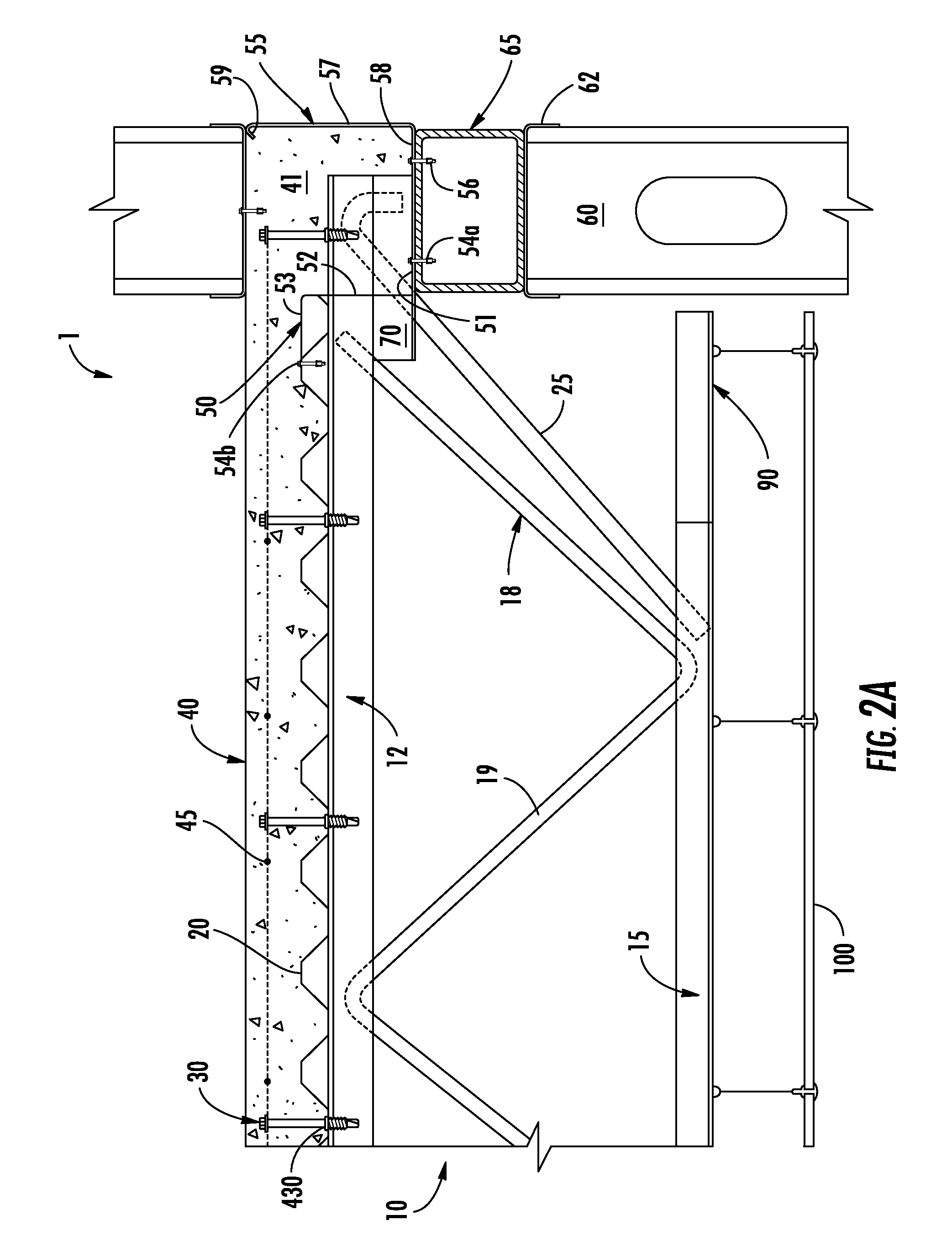
[0006]To provide additional continuity, fire protection, and stiffness at joist ends and at slab edge locations, a combination of z-shaped closures and / or pour stops provide forming for the concrete. A z-shaped closure is provided having a vertical face, an upper horizontal flange, and a lower horizontal flange. The upper horizontal flange extends over a portion of the corrugated steel decking and the lower horizontal flange is supported by the steel joist supporting member. The vertical face extends between the upper and lower horizontal flanges and has a cutout so that at least a portion of the joist end passes through the vertical face. At exterior conditions, break formed pour stops are supplied. Concrete is then placed over the corrugated steel decking and into a channel formed at least partially by the z-shaped closure and / or the pour stop.

Problems solved by technology

While joist and deck floor systems have been designed in the past to address one or more of these issues individually, these prior designs are not optimized and integrated with the portions of the support structure of a building to provide an integrated design to address the above mentioned issues in a systematic manner.

Method used


Image

  • Balcony structure
  • Balcony structure
  • Balcony structure

Examples


Embodiment Construction

[0051]Embodiments of the present invention now will be described more fully hereinafter with reference to the accompanying drawings, in which some, but not all, embodiments of the invention are shown. Indeed, the invention may be embodied in many different forms and should not be construed as limited to the embodiments set forth herein; rather, these embodiments are provided so that this disclosure will satisfy applicable legal requirements. Like numbers refer to like elements throughout.

Composite Joist Floor Systems

[0052]The composite joist floor systems described herein are generally constructed at the building site and make-up the floors and provide structural support for the ceilings of the building. In general, a plurality of joists are provided and each joist is supported at either end by the building's primary support structures, which may include but are not limited to: beams, joist girders, masonry walls, concrete walls, cold-formed wall studs, and / or wood load bearing wall...


PUM


Abstract

Systems are provided for use in balcony structures. The system includes a joist comprising an upper chord and a lower chord separated by a web. One end of the joist is supported by a supporting member and a cantilevered balcony extends generally perpendicularly from the supporting member. The cantilevered balcony comprises a cementitious balcony slab extending from a cementitious floor slab. The cementitious floor slab includes a backspan region extending from the top of the supporting member opposite the cementitious balcony slab. A portion of the joist in the backspan region comprises a decking supporting member coupled to the web between the upper chord and the lower chord. The joist in the backspan region supports decking using the decking supporting member; however, the joist beyond the backspan region supports decking above the upper chord. In this way, the cementitious floor slab in the backspan region is thicker than the cementitious floor slab beyond the backspan region.

Description

FIELD[0001]This invention relates to the field of structural systems for buildings. More particularly, embodiments of the invention relate to improved balcony structures.BACKGROUND[0002]Large scale, multi-story buildings are typically constructed of steel and concrete. Floors in such buildings may be constructed by spanning wide flange beams or steel joists between structural supports and installing metal decking across the tops of such beams or joists. The decking forms a horizontal surface onto which concrete is placed. Generally, the bottoms of the beams or joists form the framework from which ceilings are hung. The composite construction is typically achieved by using welded shear studs or partial extension of the joist top chord above the form or metal deck into the concrete slab. Flooring system designs must also be mindful of fire safety, acoustics, and vibration considerations.[0003]While joist and deck floor systems have been designed in the past to address one or more of t...

Claims


Application Information

Patent Timeline
Patent Type & Authority Patents(United States)
IPC IPC(8): E04B1/34
CPCE04B1/003E04B5/40F16B5/0275F16B25/0031F16B25/0094F16B25/103F16B33/06F16B35/048
Inventor STUDEBAKER, GLENN WAYNESAMUELSON, DAVID LEEDAYTON, LIONEL EDWARD
Owner NUCOR CORP
Learn More