Method and apparatus for mixing a gaseous fluid with a large gas stream, especially for introducing a reducing agent into a flue gas containing nitrogen oxides

Active Publication Date: 2012-01-17
FISIA BABCOCK ENVIRONMENT GMBH
View PDF18 Cites 3 Cited by
  • Summary
  • Abstract
  • Description
  • Claims
  • Application Information

AI Technical Summary

Benefits of technology

[0023]To improve the mixing process with this device, the discharge direction of the tubular admixing device is directed essentially perpendicularly onto the impact surface.

Problems solved by technology

With these procedures, there is thus no optimum distribution of the conditioning or reducing agent on the mixer disk, and there is thus no optimum mixing into the whirl system that results at the mixer disk.

Method used


Image

  • Method and apparatus for mixing a gaseous fluid with a large gas stream, especially for introducing a reducing agent into a flue gas containing nitrogen oxides
  • Method and apparatus for mixing a gaseous fluid with a large gas stream, especially for introducing a reducing agent into a flue gas containing nitrogen oxides
  • Method and apparatus for mixing a gaseous fluid with a large gas stream, especially for introducing a reducing agent into a flue gas containing nitrogen oxides

Examples


Embodiment Construction

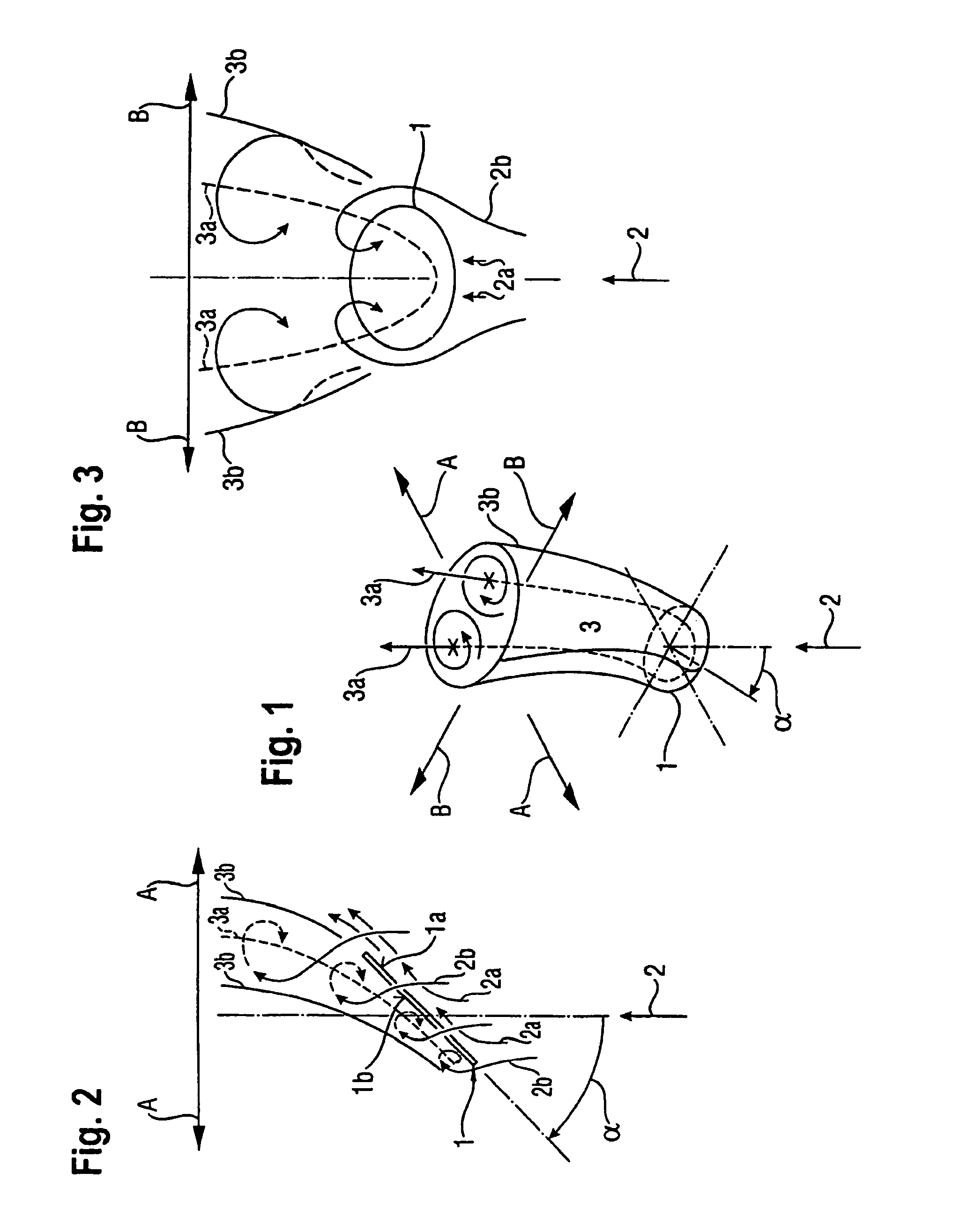
[0036]The formation, the shape and position of such eddy wakes in the downflow of mixer disks are first schematically illustrated in FIGS. 1-3 and will be described in conjunction therewith.

[0037]A circular disk 1 is inclined at an angle a relative to the flowing gas stream 2, which in FIG. 1 comes from below. On the windward or inlet side la of the disk, the gas stream is deflected from its main direction of flow, and there results a high-pressure zone. The partial stream 2a of the gas stream 2 flows at a prescribed angle along and below the disk. On the lee or discharge side 1b of the disk, a low-pressure zone forms that is filled beyond the edge of the disk by the partial stream 2a of the gas stream 2. Due to the flow deflection at the edge of the disk, there is formed a horseshoe eddy 3 having the eddy axis 3a, which is shown by a dashed line and that continues downstream of the disk in the form of an eddy wake having two symmetrically rotating eddies or whirls. The lateral eddi...


PUM

PropertyMeasurementUnit
Angleaaaaaaaaaa
Angleaaaaaaaaaa
Flow rateaaaaaaaaaa

Abstract

A method and apparatus for mixing at least one gaseous fluid stream with a large gas stream flowing in a gas duct, especially for introducing a reducing agent into a flue gas containing nitrogen oxides. The gas stream is directed against at least one disk-shaped mixer element on an inlet side that is inclined at an angle counter to the direction of flow of the gas stream, wherein eddy-type whirls form at the mixer element. The gaseous fluid stream is guided essentially to the center of an impact surface associated with the discharge side of the mixer element and is admixed with a gas stream downstream of the mixer element and is guided essentially perpendicularly onto the center of the impact surface on the discharge side such that the gaseous fluid is distributed over the entire discharge side from the center thereof and is incorporated across the entire whirl system formed at the peripheral edge of the mixer element.

Description

BACKGROUND OF THE INVENTION[0001]The instant application should be granted the priority dates of Jan. 28, 2006, the filing date of the corresponding German patent application 10 2006 004 069.4, as well as Jan. 26, 2007, the filing date of the International patent application PCT / EP2007 / 000688.[0002]The present invention relates to a method of mixing at least one gaseous fluid stream with a large gas stream, especially for introducing a reducing agent into a flue gas that contains nitrogen oxides, whereby the large gas stream flows against at least one disk-like mixer element on an inlet side (windward side) thereof, wherein the mixer element is inclined at an angle counter to the direction of flow, and wherein eddy-type whirls form at the mixer element, further according to which the fluid stream is guided essentially to the center of an impact surface that is associated with the discharge side (lee side) of the mixer element, and according to which the gaseous fluid stream is admix...

Claims


Application Information

Patent Timeline
IPC IPC(8): B01F5/04B01F23/10
CPCB01D53/8631B01D53/90F23J15/003B01F5/0451B01F5/0618B01F3/02B01D2251/20B01F23/10B01F25/3131B01F25/4316
Inventor BECKMANN, GERDENGELKING, WOLFRAMPRIESMEIER, ULRICH
Owner FISIA BABCOCK ENVIRONMENT GMBH
Why Eureka
Try Eureka