
Device and method for detecting vehicle engine pulse generator plate tooth defects

a technology for pulse generator plates and vehicles, which is applied in the direction of machines/engines, mechanical equipment, instruments, etc., can solve the problems of one or more teeth of pulse generator plates being bent or broken, not readily visible or accessible on an assembled engine, bent or otherwise damaged, etc., and achieves the effect of easy movement from engine to engine, rapid detection of damaged parts, and high portability

Inactive Publication Date: 2012-01-24
HONDA MOTOR CO LTD
View PDF11 Cites 7 Cited by
  • Summary
  • Abstract
  • Description
  • Claims
  • Application Information

AI Technical Summary

Benefits of technology

[0006]The present invention is directed to a pulse generator plate analyzer and a method of using such a device for detecting bent and / or broken teeth on a pulse generator plate of a vehicle engine. A device of the present invention generally includes a test fixture for association with an engine of interest, the test fixture having a pair of detection sensors that are operative to detect the teeth of a pulse generator plate. A device of the present invention allows for a quick an accurate determination regarding pulse generator plate tooth damage, eliminating the need to conduct a time consuming, and potentially faulty, visual inspection of the pulse generator plate.
[0011]A device of the present invention is highly portable and may be easily moved from engine to engine. Consequently, a device of the present invention can be used to quickly detect a damaged pulse generator plate without requiring time-consuming engine disassembly.

Problems solved by technology

A pulse generator plate is typically hidden behind a timing chain / belt cover and, therefore, is not readily visible or accessible on an assembled engine.
It occasionally happens that one or more teeth of a pulse generator plate become bent or broken before or during installation of the pulse generator plate and associated crankshaft to an engine block.
While a completely missing pulse generator plate tooth may be clearly visible, a tooth may be bent or otherwise damaged to an extent that interferes with its detection by a crank sensor without the damage being visually obvious (at least not without a detailed and time consuming visual inspection).
A bent or missing pulse generator plate tooth may be the source of, or contribute to, engine timing problems.
Once an engine has been assembled, it becomes more difficult to ascertain whether a pulse generator plate tooth is bent or broken.
This can be a time-consuming process that also may first require the removal of various other engine parts.

Method used


Image

  • Device and method for detecting vehicle engine pulse generator plate tooth defects
  • Device and method for detecting vehicle engine pulse generator plate tooth defects
  • Device and method for detecting vehicle engine pulse generator plate tooth defects

Examples


Embodiment Construction

)

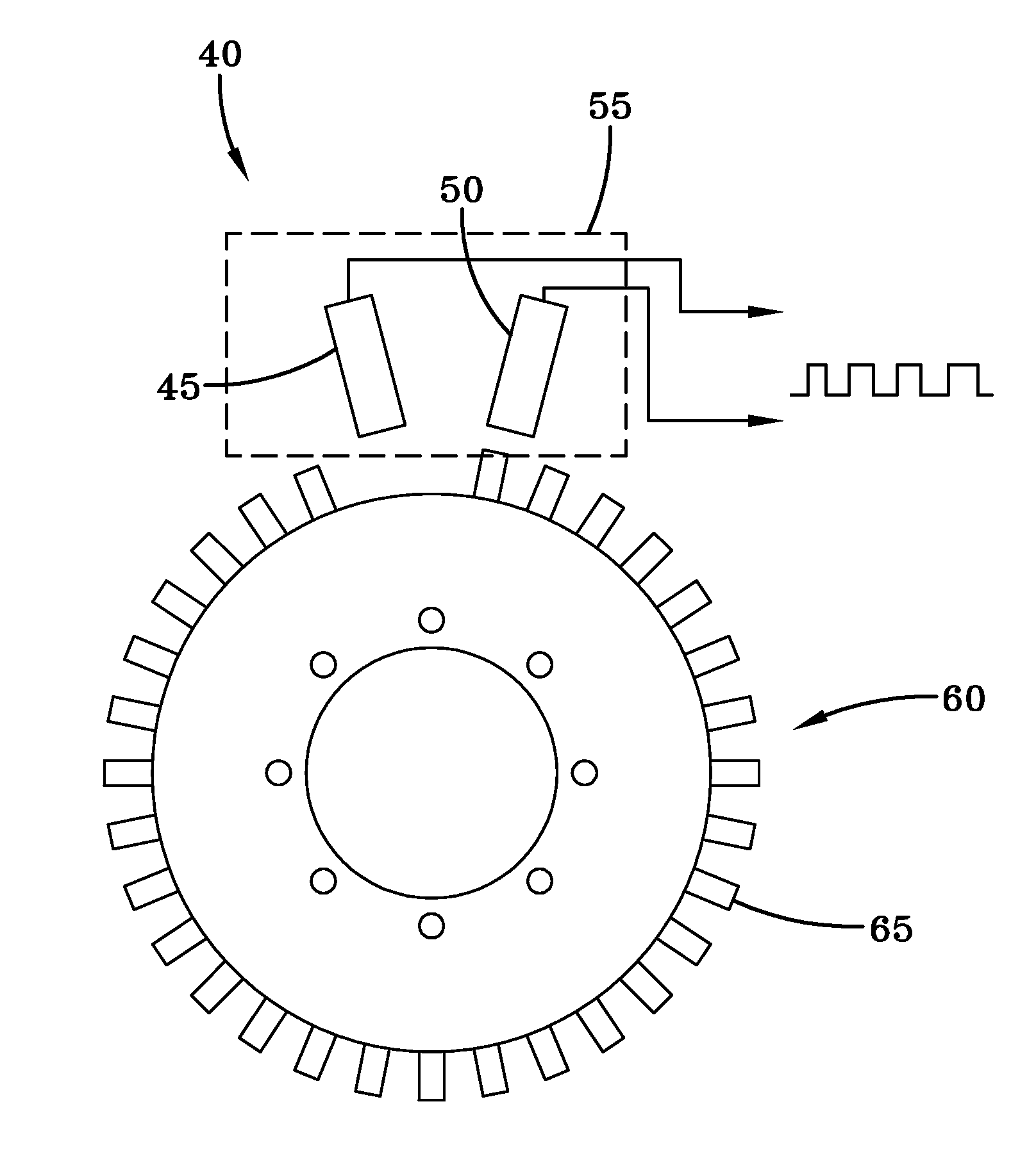
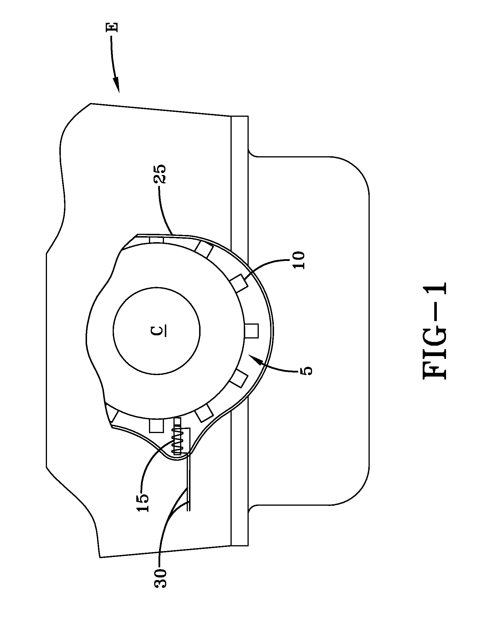
[0019]As described above, vehicle engines may employ timing systems that make use of a pulse generator plate. FIG. 1 depicts a representative pulse generator plate 5 installed to the crankshaft C of an automobile engine E. As shown, the pulse generator plate 5 is a round plate having a central aperture adapted to receive a portion of an associated crankshaft. The particular pulse generator plate 5 shown includes a number of circumferentially spaced teeth 10 that extend outward from its periphery.

[0020]In order to assist with vehicle timing, a sensor 15 is mounted near the pulse generator plate 5. The sensor 15 detects each passing of a tooth on the pulse generator plate 5. When the sensor 15 detects a tooth 10, it generates an output signal that may be sent via sensor wiring 30 to an associated vehicle computer for use in timing the vehicle's engine.

[0021]As can be observed in FIG. 1, both the pulse generator plate 5 and its associated sensor 15 are typically located within a seale...


PUM


Abstract

A device and its method of use for in situ detection of bent and / or broken teeth on a vehicle engine pulse generator plate. The device includes a pair of detection sensors adapted to detect pulse generator plate teeth during rotation of a pulse generator plate, and a controller in communication with the sensors. The sensors are arranged such that one sensor leads the other with respect to the detection of teeth on a rotating pulse generator plate. Rotation of a pulse generator plate in the presence of the sensors will cause the sensors to produce an output signal each time a tooth passes by. The signals from the sensors form associated pulse trains that are evaluated by a microprocessor device and associated program of the controller to determine if the pulse generator plate has any bent and / or broken teeth.

Description

BACKGROUND OF THE INVENTIVE FIELD[0001]The present invention is directed to a device for detecting a defective vehicle engine pulse generator plate. More specifically, the present invention is directed to a device for detecting bent or missing teeth on a vehicle engine pulse generator plate.[0002]A pulse generator plate may be coupled to a vehicle crankshaft for the purpose of timing the vehicle's engine. The design of such a pulse generator plate may vary. One known embodiment generally comprises a circular plate having a number of circumferentially spaced tabs or teeth extending therefrom. A pulse generator plate is typically hidden behind a timing chain / belt cover and, therefore, is not readily visible or accessible on an assembled engine.[0003]A sensor (e.g., crank sensor) is normally also mounted near the pulse generator plate, and is also typically enclosed within the timing chain / belt cover. The sensor produces an electrical pulse each time one of the teeth of the pulse gener...

Claims


Application Information

Patent Timeline
IPC IPC(8): G01M15/02
CPCG01D5/24457G01D5/2457
Inventor RANKIN, BRENT
Owner HONDA MOTOR CO LTD
Learn More