Flexible pipe for transporting hydrocarbons, which includes a tubular pipe carcass made of interlocked metal strip

Active Publication Date: 2012-01-24
TECH FRANCE SA
View PDF19 Cites 15 Cited by
  • Summary
  • Abstract
  • Description
  • Claims
  • Application Information

AI Technical Summary

Benefits of technology

[0020]An unexpected advantage of the invention is to do with the problem of vibrations that is found on certain flexible risers intended for producing and exporting gaseous hydrocarbons. This problem is associated with the flow of gas in rough bore pipes and more specifically with the formation of vortices which occur upon contact with the gaps between the turns of the carcass. What happens is that the surface discontinuity encountered at these gaps leads to the formation of vortices (vortex shedding) which disturb the flow of the gas through the pipe. These vortices give rise to cyclic pressure variations which may lead to problems of resonance (vibration, noise) in the pipe and in the equipment and pipework on the platform or the FPSO (Floating Production Storage and Offloading) gen

Problems solved by technology

However, owing to the relative flexibility of the profiled spacer in the longitudinal direction of the winding, the spacer does not absolute

Method used


Image

  • Flexible pipe for transporting hydrocarbons, which includes a tubular pipe carcass made of interlocked metal strip
  • Flexible pipe for transporting hydrocarbons, which includes a tubular pipe carcass made of interlocked metal strip
  • Flexible pipe for transporting hydrocarbons, which includes a tubular pipe carcass made of interlocked metal strip

Examples


Embodiment Construction

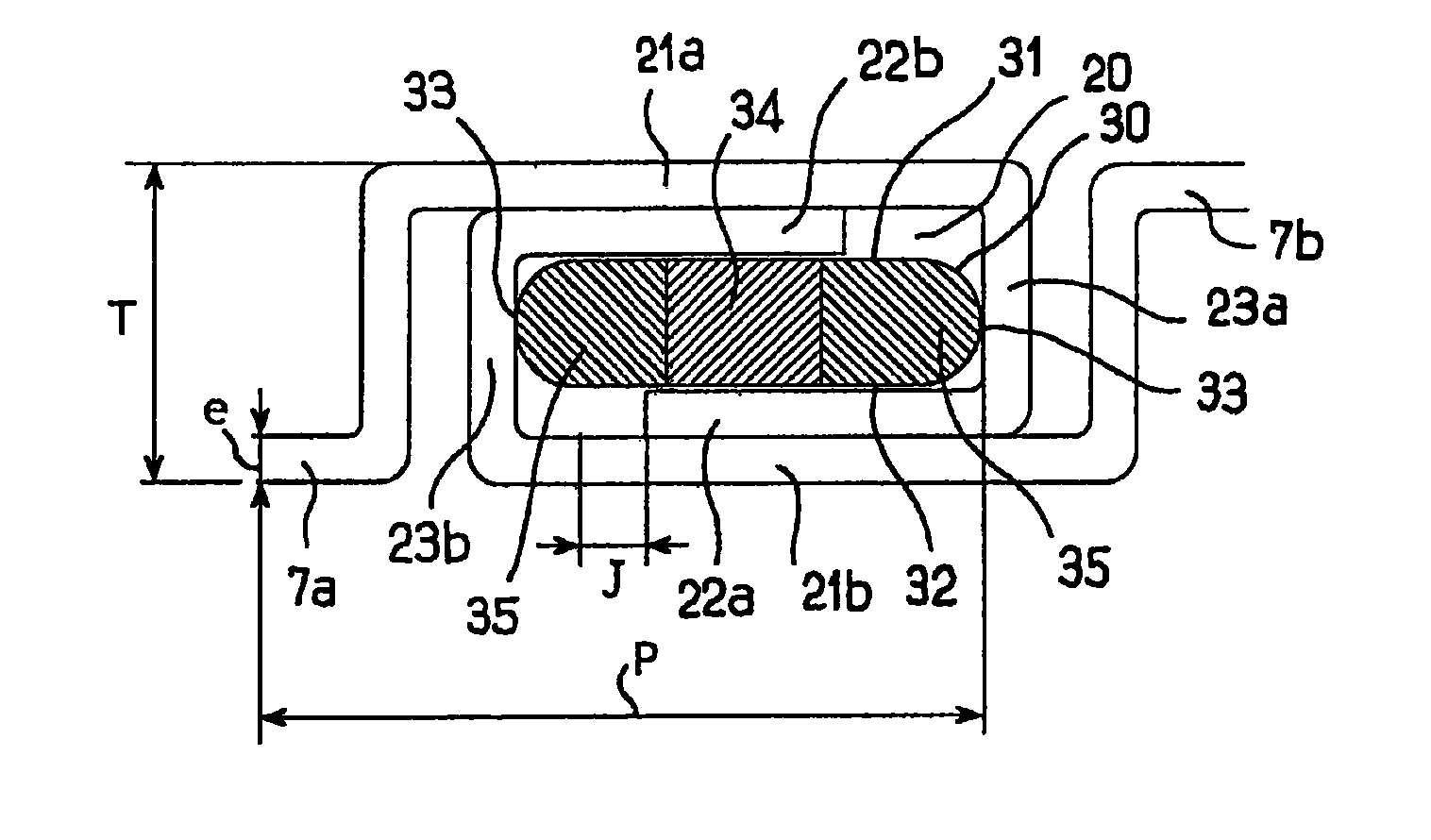
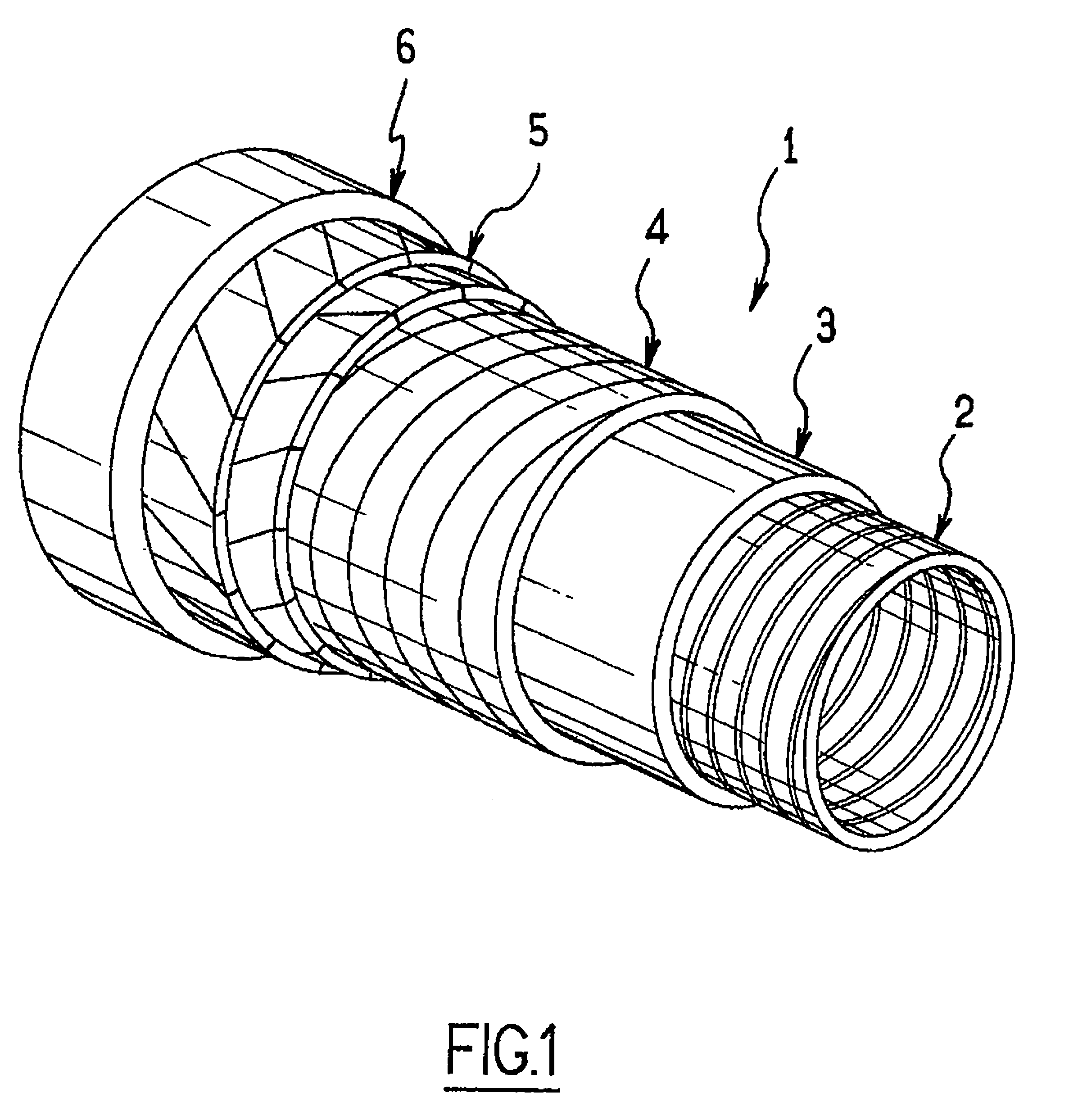
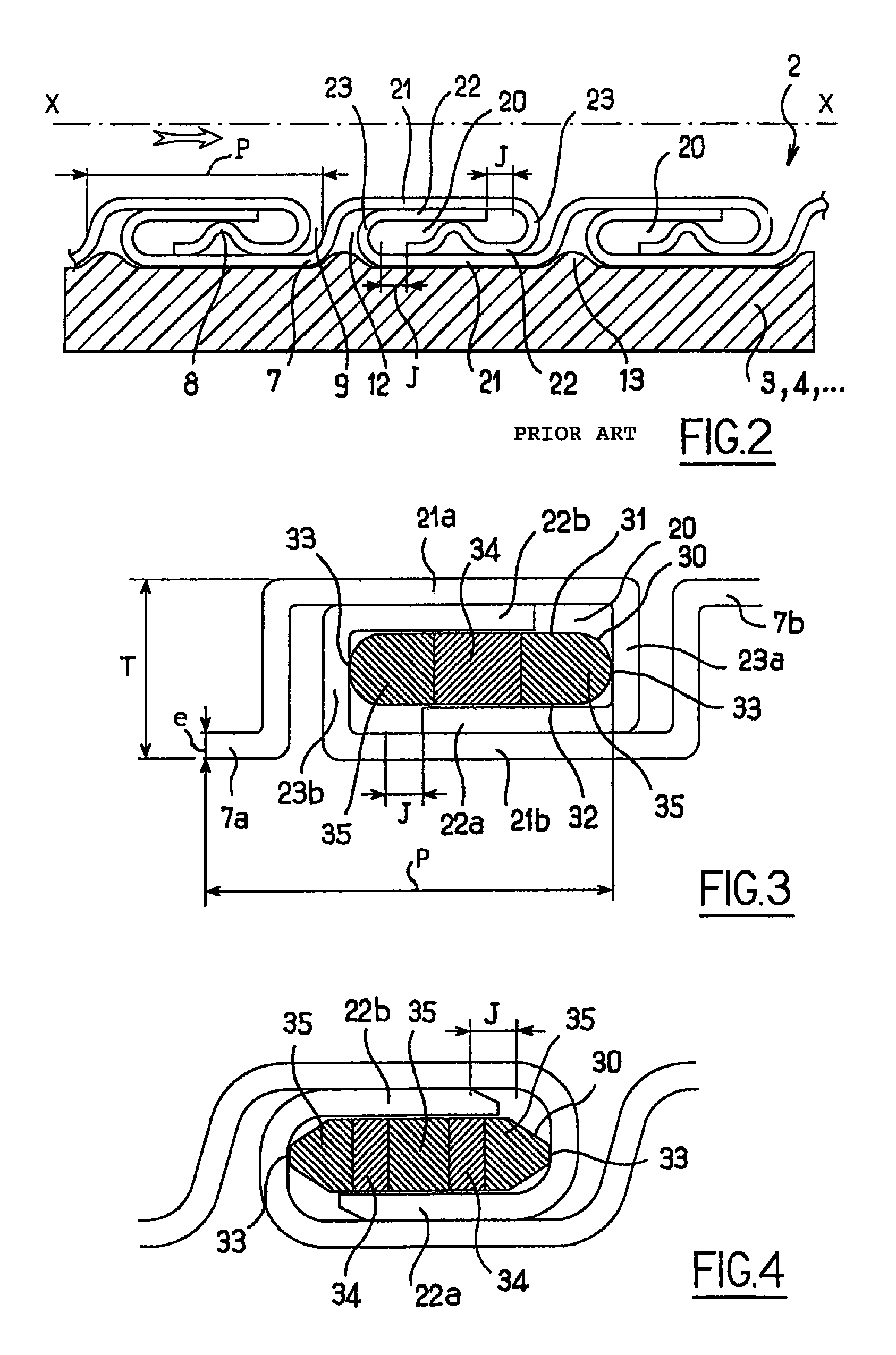
[0029]The flexible pipe 1 depicted in FIG. 1 comprises, from the inside outward:[0030]a carcass 2 consisting of an interlocked metal winding which serves to prevent the pipe from collapsing under the external pressure;[0031]an internal sealing pressure sheath 3, made of plastic, generally a polymer, resistant to the chemical action of the fluid to be transported;[0032]a pressure vault 4 that mainly resists the pressure developed by the fluid in the pressure sheath and consists of the short-pitch helical winding (that is to say with a winding angle of about 90°), about the internal sheath, of one or more interlocking metal wires (which may or may not self-interlock); the shaped wires have a cross-section in the shape of a Z or a T or any derivative (teta or zeta) thereof, of a U or of an I;[0033]at least one ply 5 (and generally at least two crossed plies) of tensile armor wound with a long pitch; the lay angle measured with respect to the longitudinal axis of the pipe is typically b...


PUM


Abstract

A flexible duct with a frame made by winding a S-profiled metal strip into clamped turns, wherein the edges of two adjacent turns overlap each other in order to form between them a helical closed space having an essentially rectangular cross-section and at least partially filled by a helically-wound spacer separate from the metal strip and resting on at least two opposing walls of the lower surface and the upper surface, wherein the spacer has, in the winding radial direction, a crush resistance substantially equal to zero and, in the winding longitudinal direction along the pipe, a substantial crush resistance.

Description

CROSS REFERENCE TO RELATED APPLICATION[0001]The present application is a 35 U.S.C. §§371 national phase conversion of PCT / FR2007 / 001369, filed Aug. 13, 2007, which claims priority of French Application No. 0607620, filed Aug. 30, 2006, incorporated by reference herein. The PCT International Application was published in the French language.BACKGROUND OF THE INVENTION[0002]The present invention relates to a flexible tubular pipe for transporting hydrocarbons, of the type comprising, placed radially from the inside outward, a carcass, an internal pressure sheath and one or more armor plies, the carcass being formed by the winding, with interlocked turns, of a profiled elongate element of metal strip type.[0003]Such a pipe is commonly called a “rough bore” pipe because the carcass which constitutes the inner layer of the pipe has obvious discontinuities at the gaps separating the turns, unlike what are called “smooth bore” pipes in which the innermost layer of the pipe is formed by an i...

Claims


Application Information

Patent Timeline
IPC IPC(8): F16L11/16
CPCF16L11/16F16L11/083
Inventor JUNG, PATRICE JOEL LOUISSECHER, PHILIPPE
Owner TECH FRANCE SA
Why Eureka
Try Eureka