
Light-emitting module and display apparatus having the same

a technology of light-emitting modules and display apparatuses, which is applied in the direction of lighting and heating apparatus, planar/plate-like light guides, instruments, etc., can solve the problems of limiting the space containing leds adjacent to the lgp, the inability to substitute known high luminance leds, and the inability to increase the width and thickness so as to achieve the effect of avoiding restrictions due to the size of the display apparatus, increasing the wiring area

Active Publication Date: 2012-01-24
SAMSUNG DISPLAY CO LTD
View PDF4 Cites 10 Cited by
  • Summary
  • Abstract
  • Description
  • Claims
  • Application Information

AI Technical Summary

Benefits of technology

The present invention provides a light-emitting module and a display apparatus with the module. The module has high luminance without increasing its size. The module includes a power transmitting substrate, a LGP, and two light sources. The power transmitting substrate has a folded shape with two substrate portions positioned perpendicular to each other. The first light source is a top view type and emits light to the light incident surface, while the second light source is a side view type and emits light to the light incident surface. The power transmitting substrate includes a flexible resin layer and power lines. The invention allows for an increased wiring area without increasing the size of the display apparatus and ensures high luminance. The light-emitting module is a hybrid type with both top view and side view type light sources. This invention is useful for a display apparatus with the edge illumination type backlight assembly.

Problems solved by technology

However, known high luminance LEDs may not be substituted for the conventional CCFLs having an L-shape, a U-shape or an O-shape, which have been used as the edge illumination type backlight assemblies.
However, a space for containing the LEDs adjacent to the LGP may be more restricted when manufacturing a slim and lightweight display apparatus.

Method used


Image

  • Light-emitting module and display apparatus having the same
  • Light-emitting module and display apparatus having the same
  • Light-emitting module and display apparatus having the same

Examples


Embodiment Construction

[0027]Although embodiments of the present invention are described more fully hereinafter with reference to the accompanying drawings, the underlying concepts may, however, be embodied in many different forms and should not be construed as limited to the exemplary embodiments set forth herein. In the drawings, the sizes and relative sizes of layers and regions may be exaggerated for sake of clarity.

[0028]It will be understood that when an element or layer is referred to as being “on,”“connected to” or “coupled to” another element or layer, it can be directly on, connected or coupled to the other element or layer or intervening elements or layers may be present. Like numerals may refer to like elements throughout.

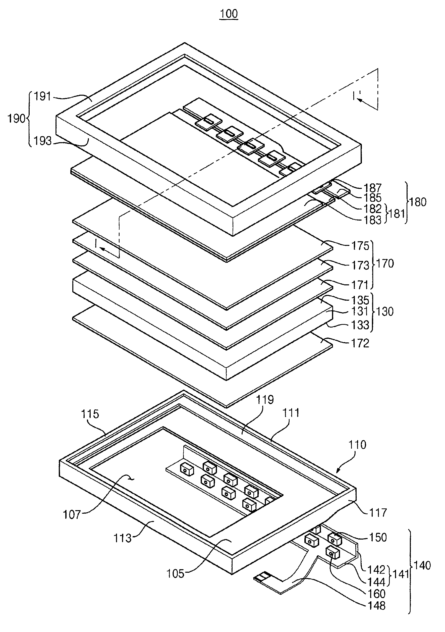
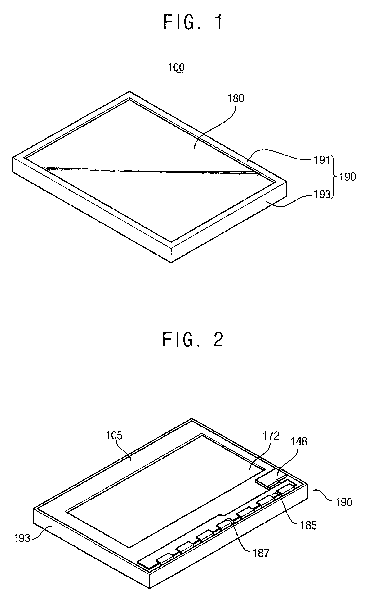
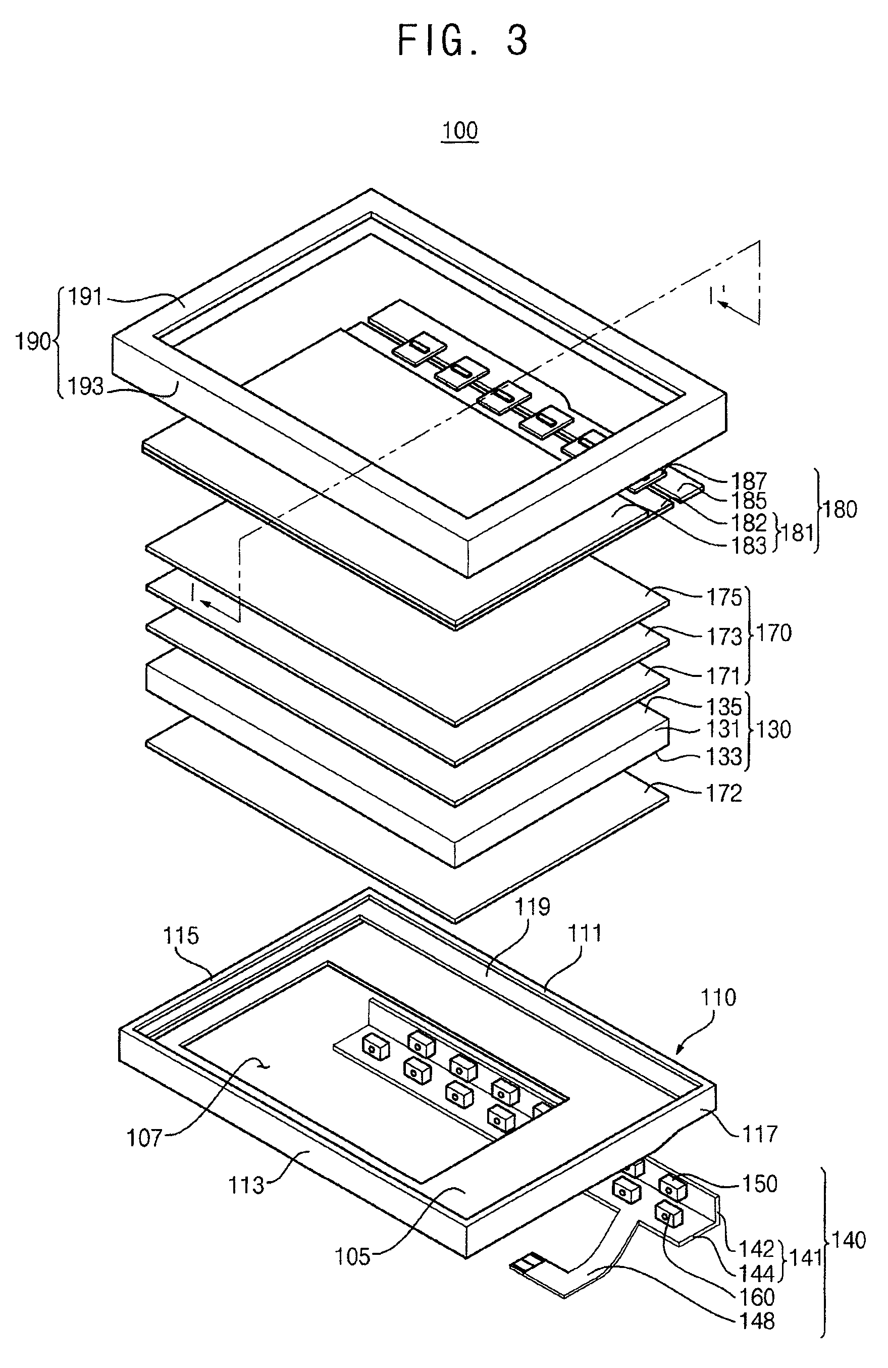
[0029]FIG. 1 is a perspective view illustrating a display apparatus 100 according to an example embodiment of the present invention. FIG. 2 is a perspective view illustrating a rear surface of the display apparatus 100 in FIG. 1. FIG. 3 is an exploded perspective view illustr...


PUM


Abstract

A light-emitting module includes a power transmitting substrate disposed adjacent to a light guide plate (LGP). The power transmitting substrate includes first and second substrate portions positioned substantially perpendicular to each other. The first substrate portion faces a light incident surface of the LGP. The second substrate portion extends from the first substrate portion and is substantially parallel with a counter surface of the LGP. First and second light sources respectively emit light from a top and a side thereof, and are respectively mounted on the first and second substrate portions. The first and second light sources respectively emit light to the light incident surface. A receiving container supports the light-emitting module and contains the LGP.

Description

PRIORITY STATEMENT[0001]This application claims priority under 35 U.S.C. §119 to Korean Patent Application No. 2008-126065, filed on Dec. 11, 2008 in the Korean Intellectual Property Office (KIPO), the contents of which are herein incorporated herein by reference in their entirety.BACKGROUND OF THE INVENTION[0002]1. Technical Field[0003]The present invention relates to a light-emitting module and, more particularly, to a light-emitting module providing light to a rear surface of a display panel and a display apparatus having the light-emitting module.[0004]2. Discussion of the Related Art[0005]A display apparatus may include a backlight assembly providing light to a display panel. A cold cathode fluorescent lamp (CCFL) has been used as a backlight source. A light-emitting diode (LED) having high luminance may be used instead of the CCFL in mid-sized display apparatuses due to the LED's eco-friendly characteristics, low power consumption and stable emitting characteristics despite va...

Claims


Application Information

Patent Timeline
Patent Type & Authority Patents(United States)
IPC IPC(8): F21V8/00
CPCG02B6/0068G02B6/0083G02B6/003G02B6/0073G02B6/009G02F1/133615G02F1/1336G02F1/133603
Inventor KIM, TAE-HOONPYOUN, SEOUNG-BUMKIM, YOUNG-JINNA, YEON-SUN
Owner SAMSUNG DISPLAY CO LTD
Learn More