Plasma processing apparatus utilizing a surface wave plasma

a processing apparatus and surface wave technology, applied in the field of surface wave plasma processing apparatus, can solve the problems of high cost, difficult processing, and unsuitable increase in the thickness and achieve the effect of not increasing the thickness and material cost of the dielectric window

Inactive Publication Date: 2005-10-11
SHIMADZU CORP
View PDF4 Cites 5 Cited by
  • Summary
  • Abstract
  • Description
  • Claims
  • Application Information

AI Technical Summary

Benefits of technology

[0009]An object of the present invention is to provide a plasma processing apparatus which can generate a plasma of a large area without increasing a thickness and material cost of a dielectric window.

Problems solved by technology

However, a high-strength dielectric material such as aluminum or zirconia has a disadvantage that it is expensive and hard to be processed.
On the other hand, it is not desirable to increase the thickness of the dielectric window because its own weight and material costs increase or it becomes susceptible to thermal shock due to a plasma.

Method used


Image

  • Plasma processing apparatus utilizing a surface wave plasma
  • Plasma processing apparatus utilizing a surface wave plasma
  • Plasma processing apparatus utilizing a surface wave plasma

Examples


first embodiment

[0033](First Embodiment)

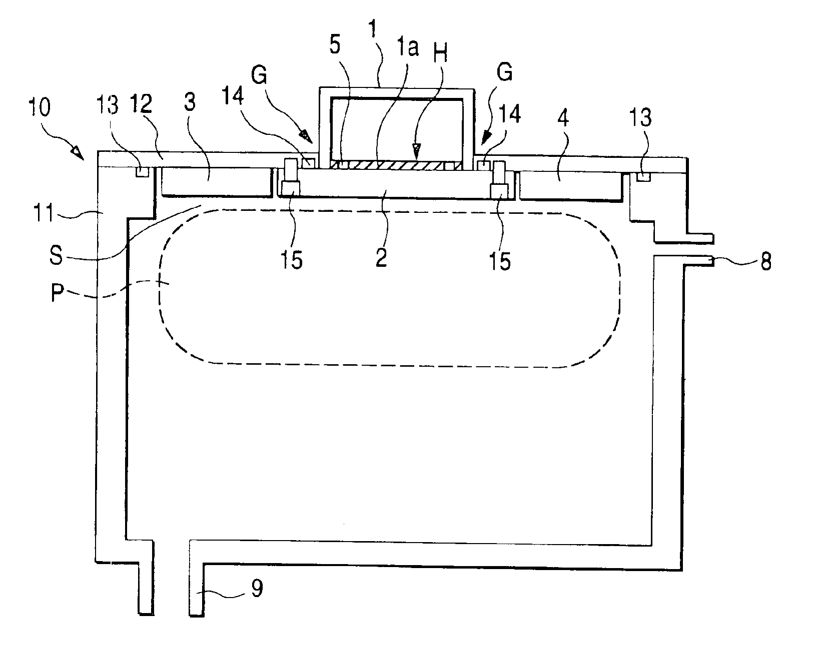
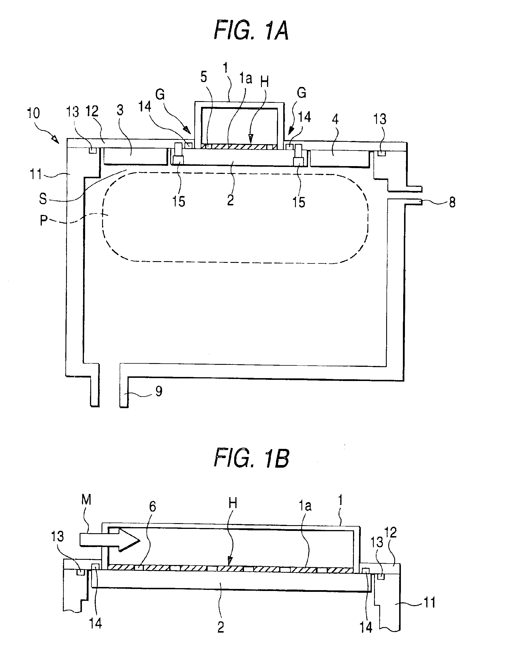
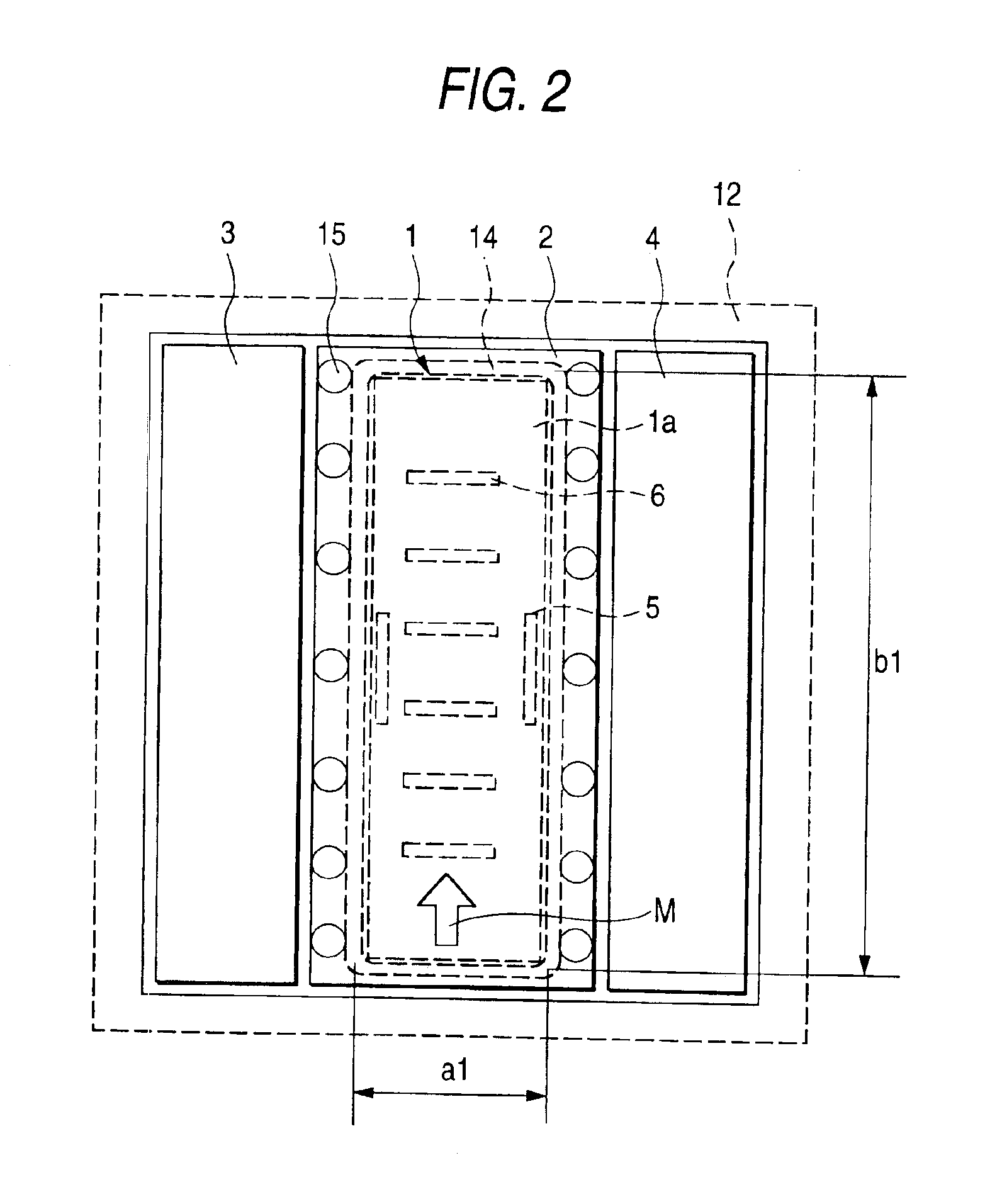
[0034]FIGS. 1A and 1B are overall diagrams schematically showing a plasma processing apparatus according to an embodiment of the present invention. FIG. 1A is a longitudinal sectional view perpendicular to an incident direction of microwaves, and FIG. 1B is a partial longitudinal sectional view parallel to the incident direction of the microwaves. FIG. 2 is a view of a dielectric plate according to the embodiment and a peripheral portion thereof viewed from an inner side of a chamber.

[0035]The plasma processing apparatus shown in FIGS. 1A and 1B and FIG. 2 includes a microwave waveguide 1, a dielectric window 2, dielectric plates 3 and 4, and a chamber 10. The dielectric plates 3 and 4 are arranged adjacent to the dielectric window 2. The dielectric window 2 and the dielectric plates 3 and 4 are dielectric members, which are processed from a dielectric material such as quartz, aluminum, zirconia, Pyrex glass (registered trademark), or Teflon (registered trade...

second embodiment

[0062](Second Embodiment)

[0063]A second embodiment will be hereinafter described with reference to FIGS. 6A to 9.

[0064]FIGS. 6A and 6B are overall diagrams schematically showing a plasma processing apparatus according to this embodiment. FIG. 7 is a view of a dielectric window and dielectric plates according to this embodiment and a peripheral portion thereof viewed from the inside of a chamber. Since FIGS. 6A and 6B and FIG. 7 are views corresponding to FIGS. 1A and 1B and FIG. 2, respectively, the same components are denoted by the identical reference numerals and signs, and differences will be mainly described.

[0065]FIG. 8 is a perspective view showing a divided shape of the dielectric window and the dielectric plates in the plasma processing apparatus according to this embodiment.

[0066]FIG. 9 is a partial sectional view for explaining an attached state of the dielectric plates according to this embodiment.

[0067]In the plasma processing apparatus according to this embodiment, the...


PUM

PropertyMeasurementUnit
pressureaaaaaaaaaa
stressaaaaaaaaaa
frequencyaaaaaaaaaa

Abstract

A dielectric window performs three functions, namely, (1) extraction of a microwave, (2) generation and transmission of a surface wave, and (3) keeping the vacuum. An O-ring, which keeps the vacuum between the dielectric window and a chamber, is arranged so as to surround the vicinity of a bottom plate 1a of a microwave waveguide. Dielectric plates area arranged in parallel with each other in the dielectric window and performs only the transmission of a surface wave. The dielectric plates may be different from the dielectric window in at least one of a shape, a thickness, and a dielectric constant.

Description

BACKGROUND OF THE INVENTION[0001]1. Field of the Invention[0002]The present invention relates to a plasma processing apparatus using a surface wave plasma.[0003]2. Description of the Related Art[0004]Plasma technique has been heretofore often used in semiconductor manufacturing processes for coating, etching, ashing, and the like. In addition, the plasma technique has been also used for manufacturing solar cells, liquid crystal displays, plasma displays, and the like. Recently, in accordance with the increase in size of a panel or a screen, a plasma processing technique of a large area has become important. For this purpose, it is necessary to generate a plasma which is large and has a uniform plasma density. If the plasma density is uniform, uniform plasma processing can be applied to an entire surface of a substrate.[0005]As a plasma processing apparatus which can generate a large plasma, there is an apparatus using a surface wave plasma (SWP) (e.g., see JP-A-2000-348898 (page 2, ...

Claims


Application Information

Patent Timeline
Patent Type & Authority Patents(United States)
IPC IPC(8): H01J37/32H05H1/46B01J19/08C23C16/511C23F4/00H01L21/02H01L21/205H01L21/3065
CPCH01J37/32192H01J37/32238H01L21/02
Inventor SUZUKI, MASAYASU
Owner SHIMADZU CORP
Why Eureka
Try Eureka