Liquid crystal display device

a liquid crystal display and display device technology, applied in the direction of discharge tube luminescnet screens, lighting and heating apparatus, instruments, etc., can solve the problems of obstructing any attempt at miniaturization of the planar size and affecting the efficiency of use of the liquid crystal display device. , to achieve the effect of increasing the luminance of the screen, reducing the thickness and the width of the liquid crystal display device, and reducing the thickness ratio

Inactive Publication Date: 2005-12-08
PANASONIC LIQUID CRYSTAL DISPLAY CO LTD +1
View PDF7 Cites 5 Cited by
  • Summary
  • Abstract
  • Description
  • Claims
  • Application Information

AI Technical Summary

Benefits of technology

[0033] By disposing two cold cathode fluorescent tubes, which constitute linear light sources, in a lateral arrangement, it is possible to increase the luminance of a screen. Further, it is possible to implement a pull-around disposition of the power supply cables, which becomes necessary due the arrangement of the cold cathode fluorescent tubes, without increasing the thickness and the width of the liquid crystal display device. Further, by providing the both-surface reflection plate between two cold cathode fluorescent tubes, it is possible to efficiently make use of light irradiated from the cold cathode fluorescent tube on a side remote from the light guide plate, thus realizing a liquid crystal display device having a higher luminance.

Problems solved by technology

Further, in an attempt to pull around these cables in the narrow space defined between the back surface of the light reflection plate RFP and the inner wall of the lower casing BCS, as well as in the inside of the vertical-directional sizes of the light reflection plate RFP, the cables interfere with each other, and, hence, it is extremely difficult to house these cables in the inside of the vertical-directional sizes of the light reflection plate RFP.
Although the cables can be pulled out in the longitudinal direction of the cold cathode fluorescent tubes, in this case, the width of the backlight (the length of the light source portion) largely projects from the width dimension of the liquid crystal panel, and, hence, the picture frame size is increased, thus obstructing any attempt at miniaturization of the planar size of the liquid crystal display device.

Method used


Image

  • Liquid crystal display device
  • Liquid crystal display device
  • Liquid crystal display device

Examples


embodiment 1

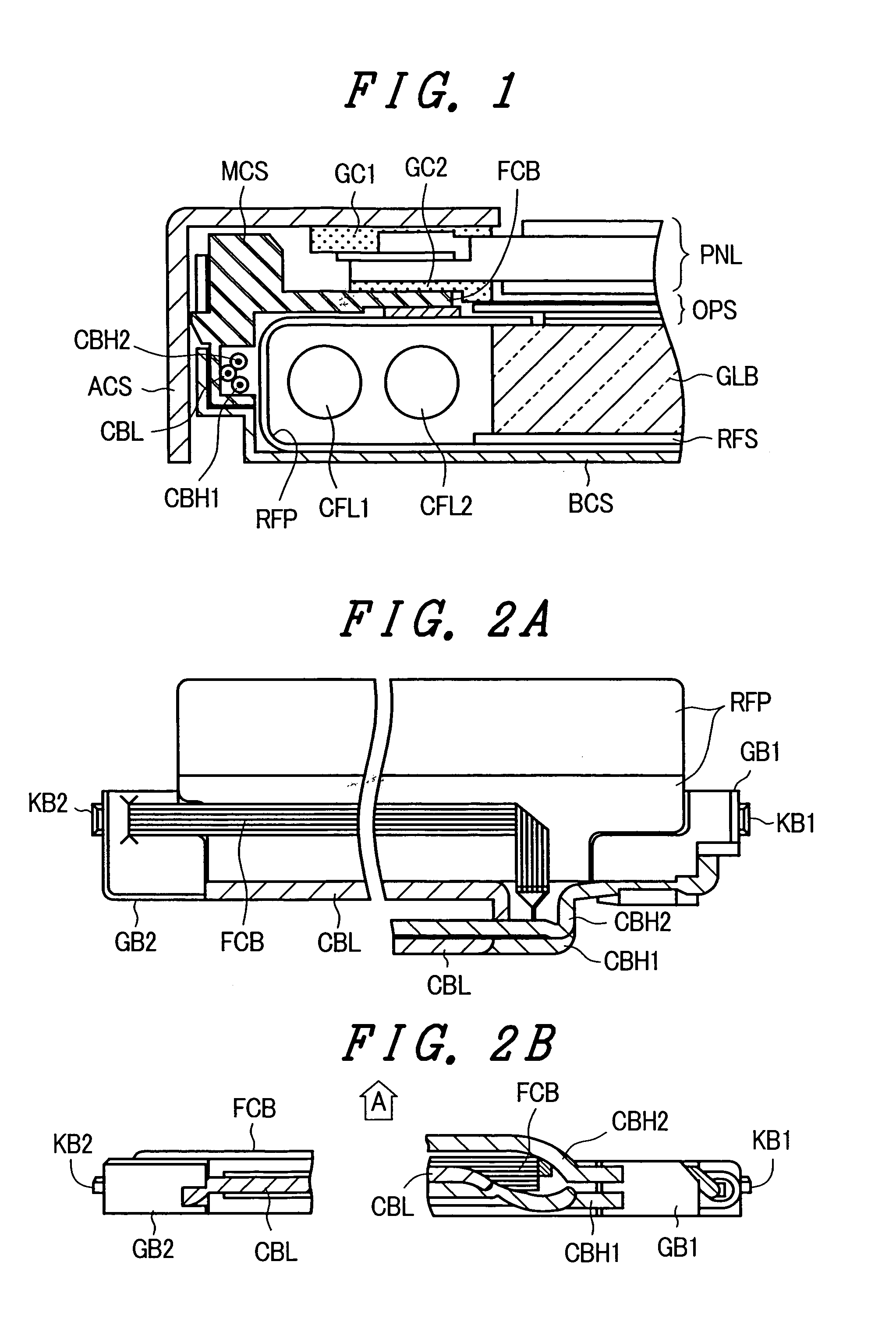
[0046]FIG. 1 is a cross-sectional view showing the structure of part of a liquid crystal display device according to an embodiment 1 of the present invention, which device is provided with a backlight having two cold cathode florescent tubes that are arranged on one side of a light guide plate. As seen in FIG. 1, in the liquid crystal display device, the backlight BL is arranged on a back surface of a liquid crystal panel PNL. An optical compensation sheet OPS, which is formed by stacking prism sheets, and light diffusion sheets is interposed between the liquid crystal panel PNL and the backlight BL.

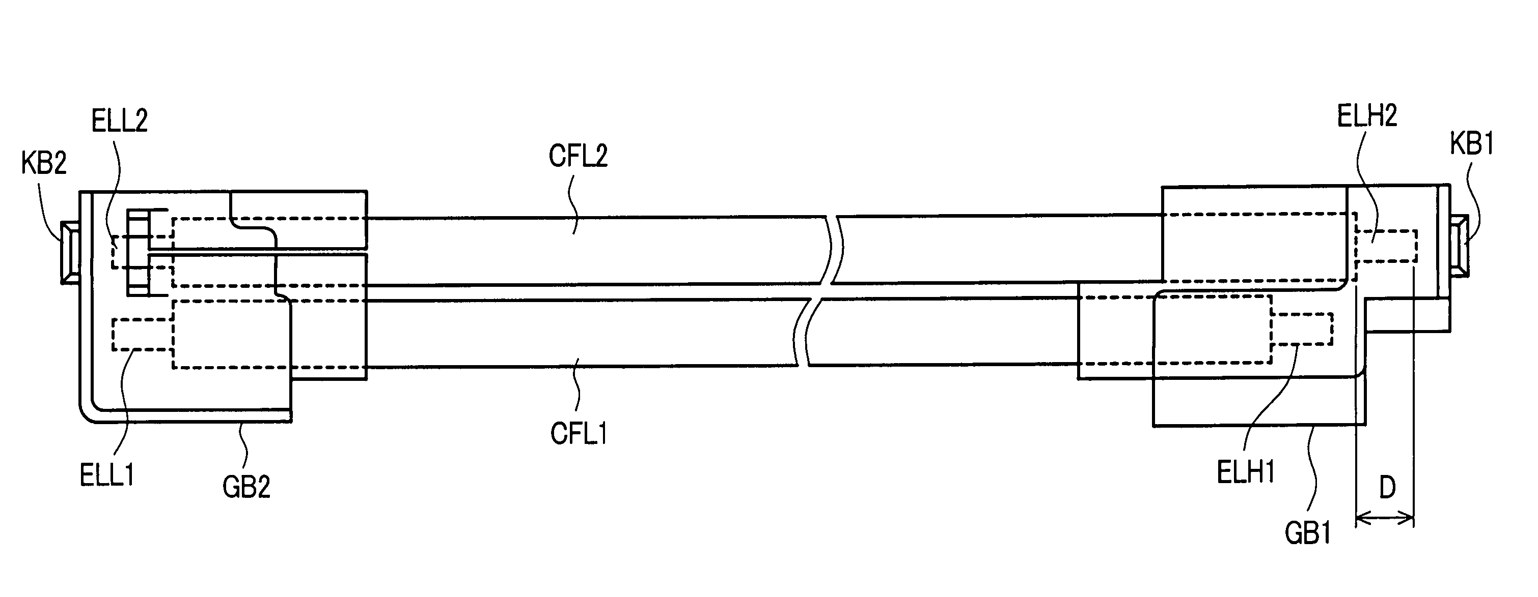
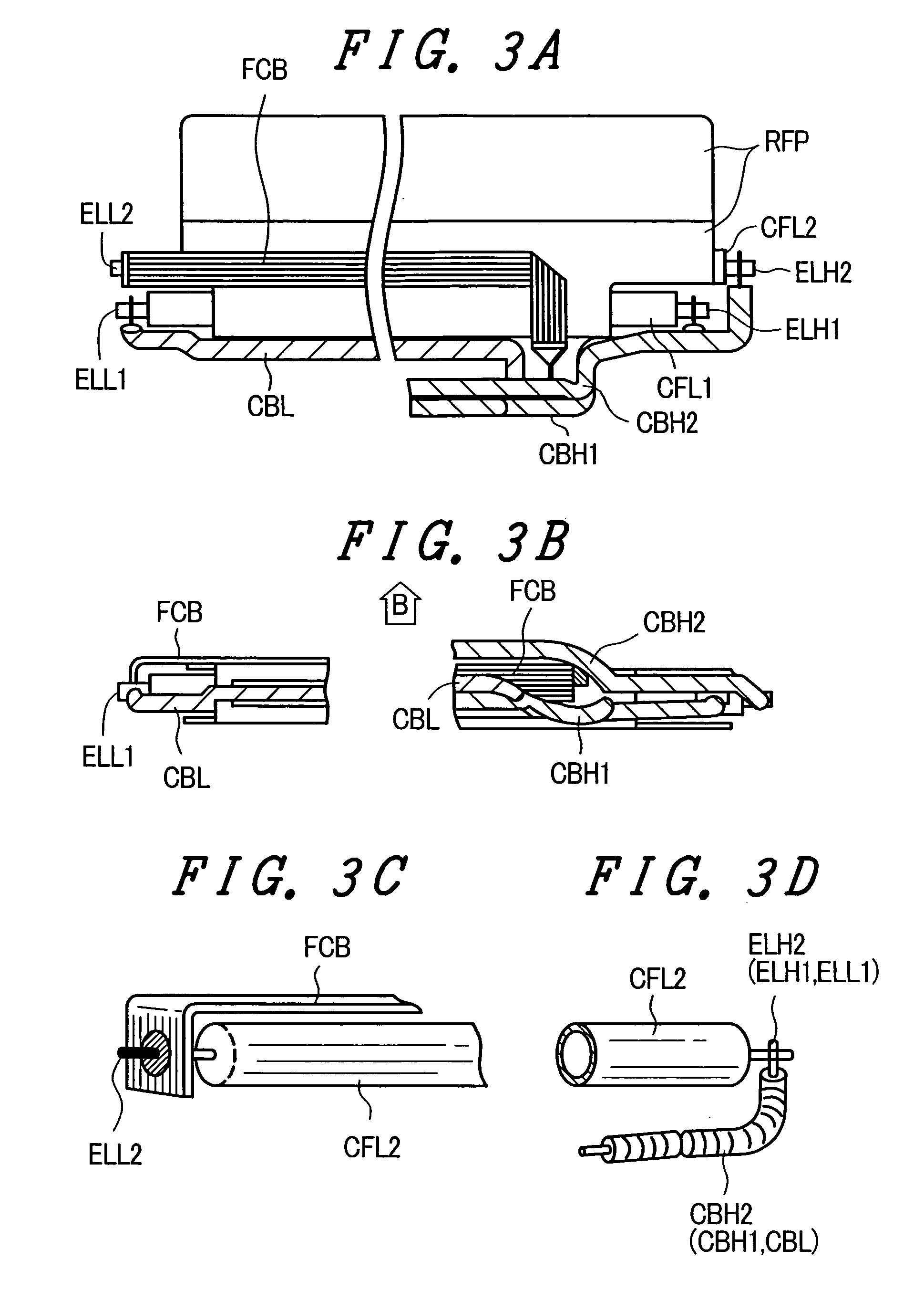
[0047] The liquid crystal display device has substantially the same structure as the liquid crystal display device shown in FIG. 9, except for the cold cathode florescent tubes, which constitute a linear light source, and the pull-around structure of the power supply cables; hence, a repeated explanation of the common elements is omitted. Here, symbol FCB indicates a flat cable.

[0048] ...

embodiment 2

[0058]FIG. 5A and FIG. 5B are views of an embodiment 2 of the present invention in which two cold cathode fluorescent tubes are arranged on one side of a light guide plate, wherein FIG. 5A is a cross-sectional view of a liquid crystal display device including the structure of the part thereof where the fluorescent tubes are located, and FIG. 5B is a partial cross-sectional view showing another possible arrangement of the cold cathode fluorescent tubes. The embodiment 2 is substantially the same as the embodiment 1 shown in FIG. 1, except for the point that a both-surface reflection plate RFM is arranged between the first cold cathode fluorescent tube CFL1 and the second cold cathode fluorescent tube CFL2.

[0059] In this embodiment, as shown in FIG. 5A, between the first cold cathode fluorescent tube CFL1 and the second cold cathode fluorescent tube CFL2, which are arranged in parallel along at least one side of the light guide plate GLB, the both-face reflection plate RFM, which has...


PUM

PropertyMeasurementUnit
voltageaaaaaaaaaa
brightnessaaaaaaaaaa
colorsaaaaaaaaaa

Abstract

In a liquid crystal display devices, a reduction in thickness with high luminance is achieved by laterally arranging two cold cathode fluorescent tubes in parallel to a main surface of the light guide plate along one side thereof and, at the same time, mutual interference in the pull-around disposition of power supply cables is eliminated. One of the cold cathode fluorescent tubes has a high-voltage-side electrode terminal thereof connected with one end of a high-voltage-side cable and a low-voltage-side electrode terminal thereof connected with one end of a flat cable. The flat cable has a midst portion mid-portion thereof bent at 90 degrees, and it traverses a lamp reflection plate, is further twisted at 90 degrees in the longitudinal direction, is further bent at 90 degrees and is merged with a pull-around path of the high-voltage-side cables.

Description

BACKGROUND OF THE INVENTION [0001] The present invention relates in general to a liquid crystal display device, and, more particularly, the invention relates to a liquid crystal display device which includes a side-edge-type backlight that is capable of producing a high brightness by use of two or several linear light sources. [0002] The liquid crystal display device is constituted of a pixel selection circuit and a liquid crystal panel in which a liquid crystal layer is interposed between two substrates, wherein a plurality of color filters are formed on one of the two substrates. With respect to the liquid crystal panel which constitutes the liquid crystal display device, various types of liquid crystal panels have been put into practical use. For example, an active matrix type liquid crystal display panel includes one substrate (also referred to as a TFT substrate), on which thin film transistors (TFT) for pixel selection are mounted, and another substrate (also referred to as a ...

Claims


Application Information

Patent Timeline
Patent Type & Authority Applications(United States)
IPC IPC(8): G02F1/13357F21V8/00F21Y103/00G02F1/1345H01J1/62
CPCG02B6/0068G02B6/009G02B6/0083G02B6/0071
Inventor MITSUHASHI, NOBUYUKIHARAYAMA, TAKESHIENOMONO, TETSUYA
Owner PANASONIC LIQUID CRYSTAL DISPLAY CO LTD
Why Eureka
Try Eureka