
Electronically controlled locking differential having logic-control wire harness

a technology of logic control and locking differential, which is applied in the direction of relays, transportation and packaging, gearing, etc., can solve the problems of premature wear of differential and related parts, premature death of battery of 4wd vehicles, and unnecessarily powering differentials, etc., to achieve the effect of prolonging the life of batteries

Active Publication Date: 2012-01-24
EATON INTELLIGENT POWER LTD
View PDF16 Cites 5 Cited by
  • Summary
  • Abstract
  • Description
  • Claims
  • Application Information

AI Technical Summary

Benefits of technology

[0008]The electronically controlled locking differential of the present invention provides control, power, traction, and off-road performance to a 4WD vehicle. Also, momentary “on / off” latching and drop-out power of the differential is controlled. And, actuation of the differential is prevented when 4WD functionality of the vehicle is not desired or necessary or the 4WD vehicle is not traveling relatively slowly. Furthermore, operation of the differential is logically controlled such that the differential is automatically disengaged and, thus, unlocked when the 4WD vehicle is out of first gear or reverse. In addition, wear of the differential and related parts and an axle and corresponding tires of the 4WD vehicle is not premature. Moreover, since the differential resets when power to the 4WD vehicle is turned off, the differential helps provide longer life to a battery of the vehicle. Plus, the harness of the differential can be a part of an aftermarket electronically-actuated-locking-differential system. The harness of the differential can be employed with OEM applications as well.

Problems solved by technology

In practice, the differential may remain unnecessarily powered, possibly for even a substantial length of time before the driver deactivates the switch.
Furthermore, if the differential remains powered when the vehicle is turned off, the differential is automatically re-powered when the vehicle is turned back on, even when operation of the differential is not actually desired.
In addition, the driver may inadvertently bump and, thus, dangerously activate the switch when the vehicle is traveling at highway speeds, say, 70 mph.
In any event, unnecessary operation of the differential causes unnecessary locking of an axle of the 4WD vehicle when it is moving, which, in turn, causes premature wear of the differential and related parts and the axle and corresponding tires.
Moreover, as a consequence of the differential frequently being powered unnecessarily for extended periods of time, the battery of the 4WD vehicle may prematurely die.

Method used


Image

  • Electronically controlled locking differential having logic-control wire harness
  • Electronically controlled locking differential having logic-control wire harness
  • Electronically controlled locking differential having logic-control wire harness

Examples


Embodiment Construction

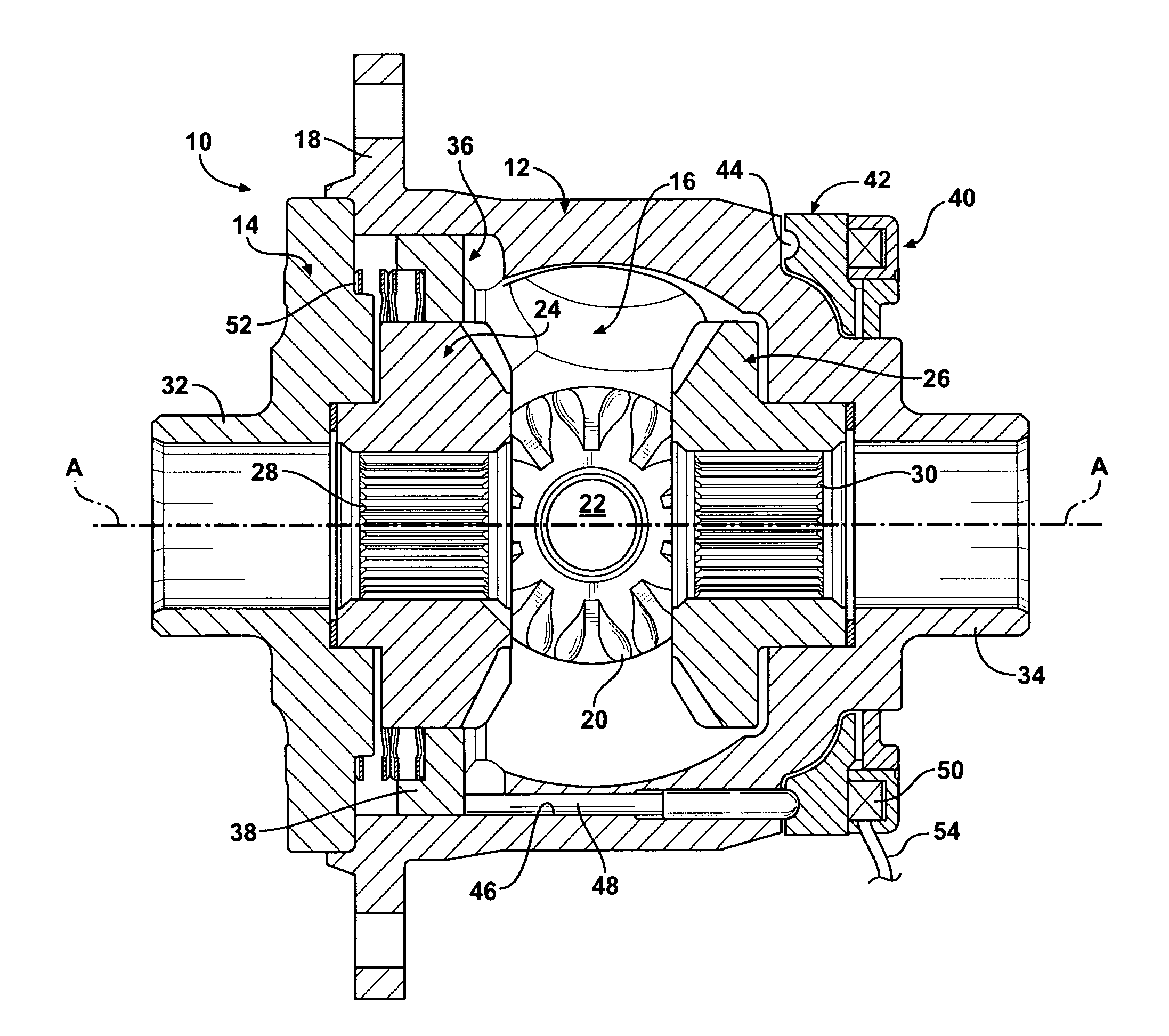
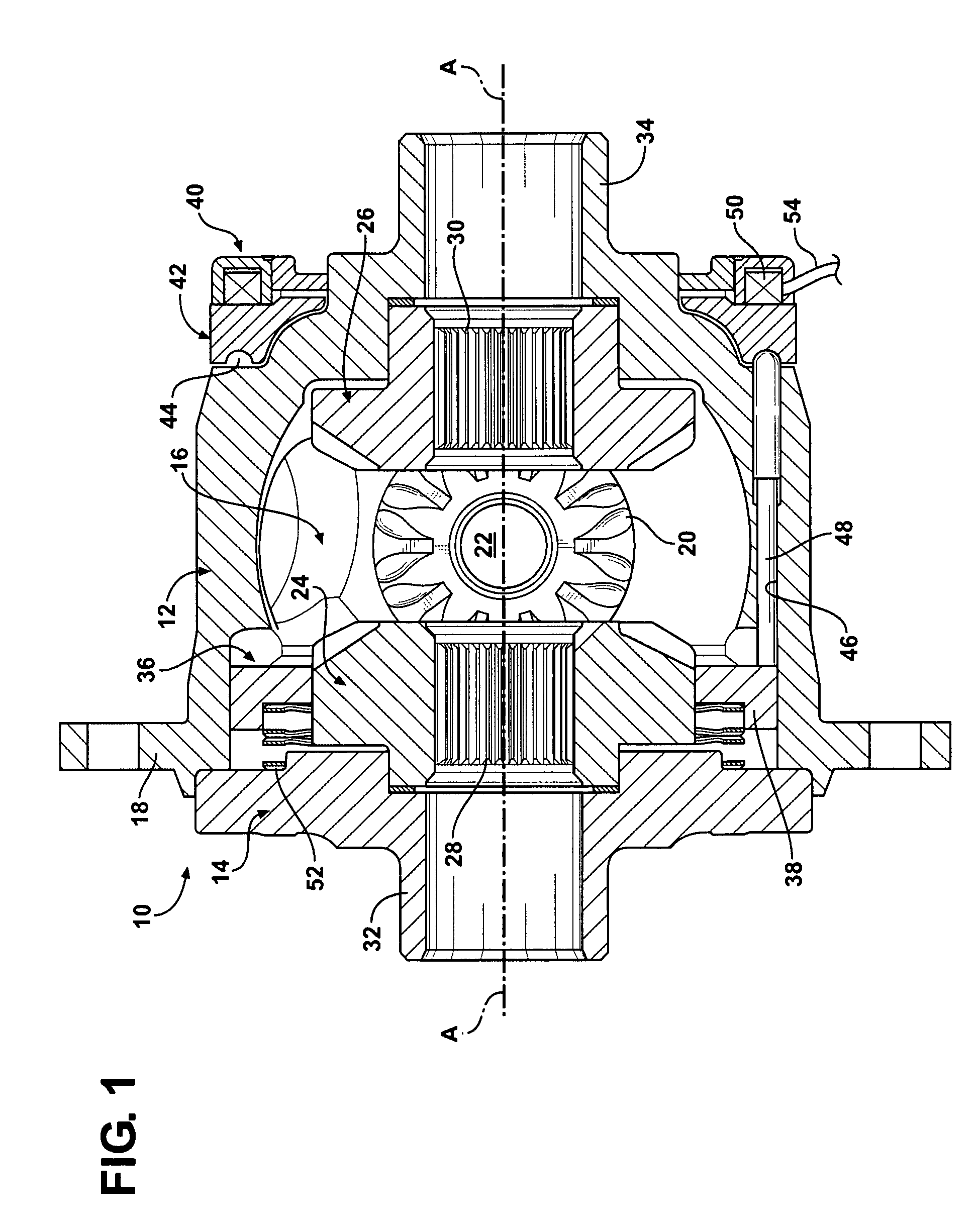
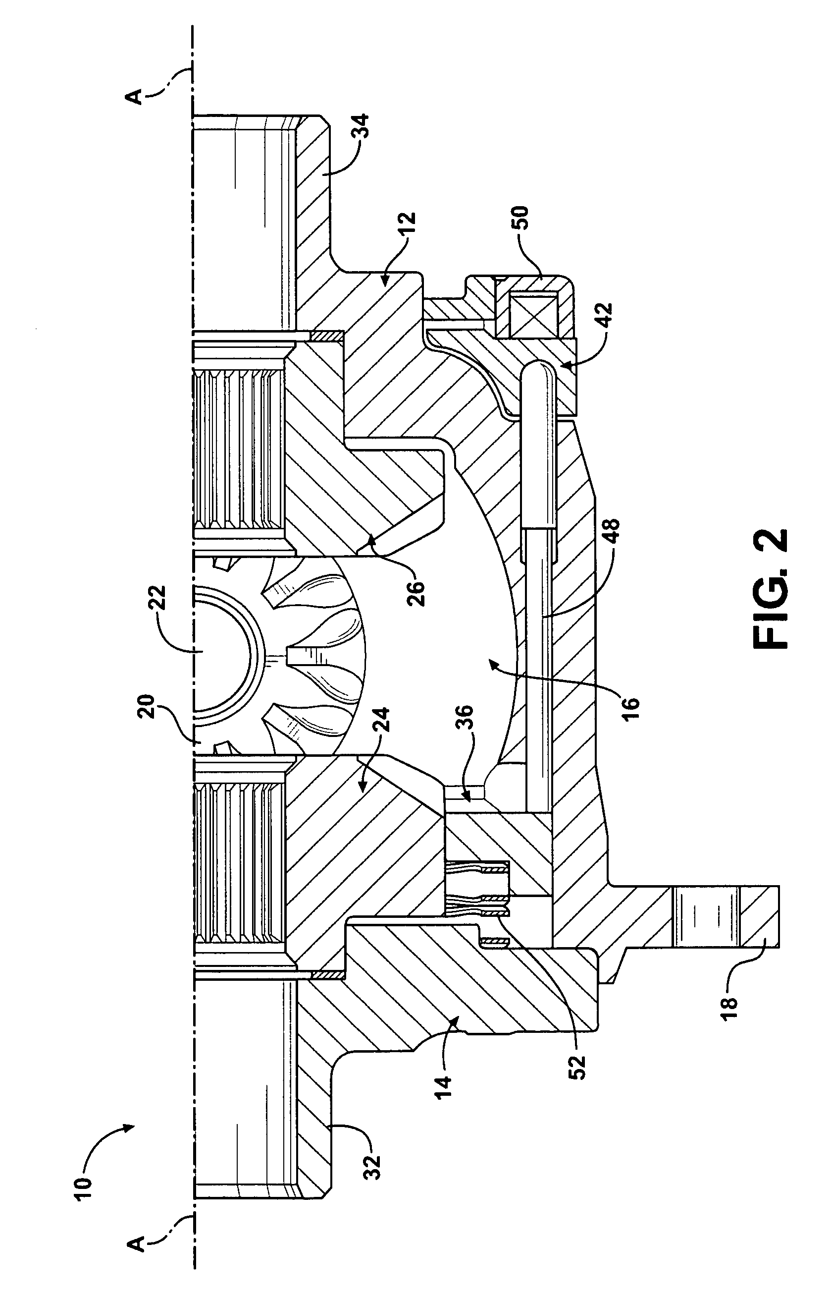
[0013]Referring now to the figures, where like numerals are used to designate like structure, one embodiment of an electronically controlled locking differential that the wire harness of the present invention can logically control is generally indicated at 10. It should be appreciated by those having ordinary skill in the related art that the differential 10 can be employed in 4WD vehicles, in particular, and any suitable vehicles, in general. It should also be appreciated that the wire harness of the present invention can be employed with any suitable electronically controlled locking differential. The one described below and shown in FIGS. 1 and 2 is only exemplary, and the wire harness can be employed with an electronically controlled locking differential that is structurally and functionally different than this one. It should also be appreciated that the wire harness can be employed by an OEM or the aftermarket. In the latter case, the wire harness is only part of a system that ...


PUM


Abstract

An electronically controlled locking differential includes an electromagnetic coil and a wire harness adapted to logically control operation of the differential and having a circuit. The circuit has a latching switch that is electrically connected to a first source of power and adapted to provide latching power of the differential. A double-pole, double-throw control relay is electrically connected to the latching switch and includes a first switch, a second switch, and a coil. The second switch is adapted to “jump” the latching switch. The circuit is disabled when power to the harness is turned off and in “standby” mode when power to the harness is turned on. Upon the latching switch being activated, current flows from a starting point of the circuit through the circuit to activate the relay, the first switch closes to energize the differential, the second switch closes such that the current “jumps” the latching switch, and the differential is actuated.

Description

BACKGROUND OF THE INVENTION[0001]1. Field of the Invention[0002]The present invention relates, in general, to electronically controlled locking differentials and, in particular, to an electronically controlled locking differential having a wire harness adapted to logically control operation of the differential.[0003]2. Description of the Related Art[0004]In automotive applications, an electronically controlled locking differential of the related art may be actuated manually and is designed expressly for a four-wheel-drive (4WD) vehicle to allow the differential to be locked or unlocked when it is so desired. The driver can lock the front and / or rear wheels by manually activating a switch or button mounted to a dash or console of the vehicle. This type of torque-controlling device is well-known in the aftermarket. More specifically, an aftermarket system including the differential can be installed using a wire harness, a gear-service kit, locking-mechanism kit, stator / armature kit, a...

Claims


Application Information

Patent Timeline
Patent Type & Authority Patents(United States)
IPC IPC(8): F16H48/30F16H48/20
CPCB60K23/04F16H48/30F16H48/24F16H2048/346F16H2048/204
Inventor DAYTON, TERRY ANDREW
Owner EATON INTELLIGENT POWER LTD
Learn More