Active-radar-assisted passive composite imagery for aiding navigation or detecting threats

a technology of active radar and composite imagery, applied in the field of electromagnetic imaging, can solve the problems of ineffective navigational system, impaired visual and ir devices, and severe inability to achieve passive imaging devices

Inactive Publication Date: 2012-01-24
NAVY THE UNITED STATES OF AMERICA SEC OF THE
View PDF24 Cites 49 Cited by
  • Summary
  • Abstract
  • Description
  • Claims
  • Application Information

AI Technical Summary

Benefits of technology

[0018]The present invention, as typically embodied, uniquely features, inter alia: radar to locate a target and to assess the target's ambient conditions in terms of obscuration (especially, horizontal obscuration); light measurement to assess the target's ambient conditions in terms of visible lighting; processing of the radar data to direct non-radar electromagnetic sensors to the target; and, processing of the radar data and the light measurement data to help optimize the fusion of the respective images of the non-radar electromagnetic sensors.
[0021]An inventive imaging system as typically embodied includes an active sensor component (i.e., radar), at least three passive sensor components, and a visible light measurement component. The radar performs functions including detection of an object, aiming (directing) of passive sensor components toward the object, and environmental assessment for optimizing data fusion of respective images of the object from plural passive sensor components. The visible light measurement component also furthers optimization of the data fusion.
[0025]Under favorable conditions, passive EO / LI, passive MWIR, and passive LWIR imaging devices individually have excellent resolution. The passive MWIR and passive LWIR devices can identify heat sources, thus imparting additional information to the compositely rendered scene. The resolution of passive mmW is moderate as compared with passive EO / LI or passive IR; nevertheless, inclusion of a passive mmW device, which can see (and hence to some degree be informative) under almost any environmental conditions, practically assures the operational usefulness of the inventive imaging system under even the most extreme inclement weather conditions.
[0028]According to frequent inventive practice, the environmental data pertaining to obscuration (radar data) and lighting (time data and / or visible light sensor data) are the two main criteria for choosing the appropriate algorithm for fusing images from among different sensors within the visual, IR, and mmW regions of the electromagnetic spectrum. An operational mode defining modal indices is selected based on the criteria. An algorithm is thus chosen that corresponds to the selected operational mode so as to correspondingly attribute weights (as indicated by the modal indices) to the imaging data from the respective sensors. As the environmental data pertaining to obscuration and lighting changes over time, the inventive system can smartly adapt in real or near-real time so as to adjust the setting to a fusion algorithm that is more or most fitting.
[0031]According to some inventive embodiments, the location of the target as sensed by a radar device is an additional criterion for choosing the appropriate image fusion algorithm, since different spectral regions may have different properties at different propagative distances. The light measurement component assists the multispectral imaging by sensing ambient visual light conditions, the radar component assists the multispectral imaging by sensing ambient atmospheric conditions, and the target location component assists the multispectral imaging by sensing the distance of the target from the sensing devices. The operational modes are based on the radar's environmental reading, the radar's target position reading, and the amount of ambient daylight. As the environmental data pertaining to obscuration and lighting changes over time, and / or the target location data changes over time, the inventive system can smartly adapt in real or near-real time so as to adjust the setting to a fusion algorithm that is more or most fitting.

Problems solved by technology

Operational effectiveness of passive (non-transmitting) imaging devices can be severely inhibited by atmospheric obscurants (e.g., particulate matter) characterizing inclement weather or air pollution.
Visual and IR devices are impaired by adverse conditions (e.g., inclement weather) and are thus ineffective for navigational systems under such conditions.
Of all of the imaging devices, visual light devices can afford the highest image detail; on the other hand, visual spectrum systems operate during daytime only, are impaired by adverse weather / particulates, and are limited in range by the visual acuity of the device and the size of the target.
Similarly, IR devices provide good image detail, can be impaired by adverse weather / particulates, and are limited in range by the visual acuity of the device and the size of the target; however, as distinguished from visual devices, IR devices can operate in either day or night.
Like IR devices, mmW devices can operate in either day or night; unlike IR devices, mmW devices afford marginal image detail, can operate in all weather / particulate conditions, and are limited to short range use.
However, radar provides no image detail, and active radar is limited to line-of-sight sensing.
This actively emitted radar energy can be collected by other sensors, and thus can be counterproductive to concealment of the entity (e.g., ship or other vehicle) from which the radar is being transmitted.

Method used


Image

  • Active-radar-assisted passive composite imagery for aiding navigation or detecting threats
  • Active-radar-assisted passive composite imagery for aiding navigation or detecting threats
  • Active-radar-assisted passive composite imagery for aiding navigation or detecting threats

Examples


Embodiment Construction

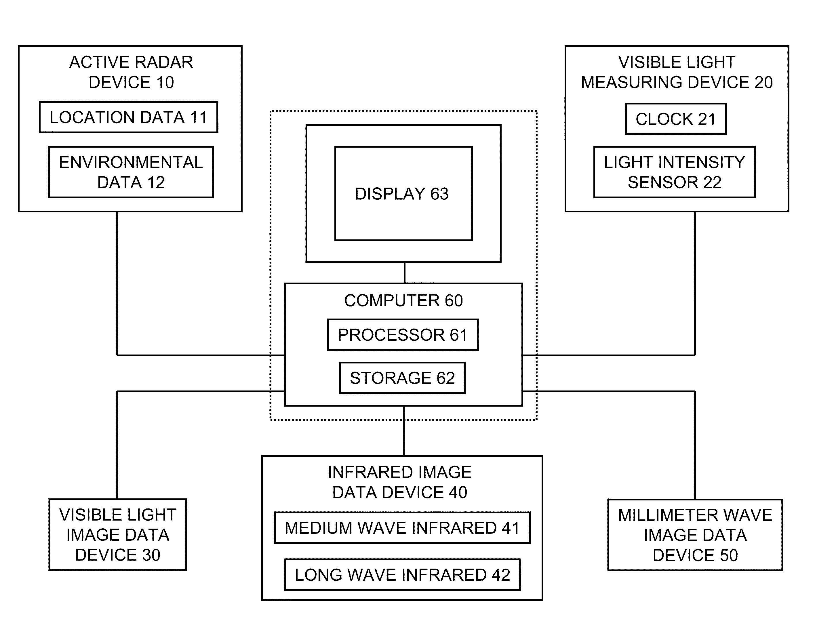
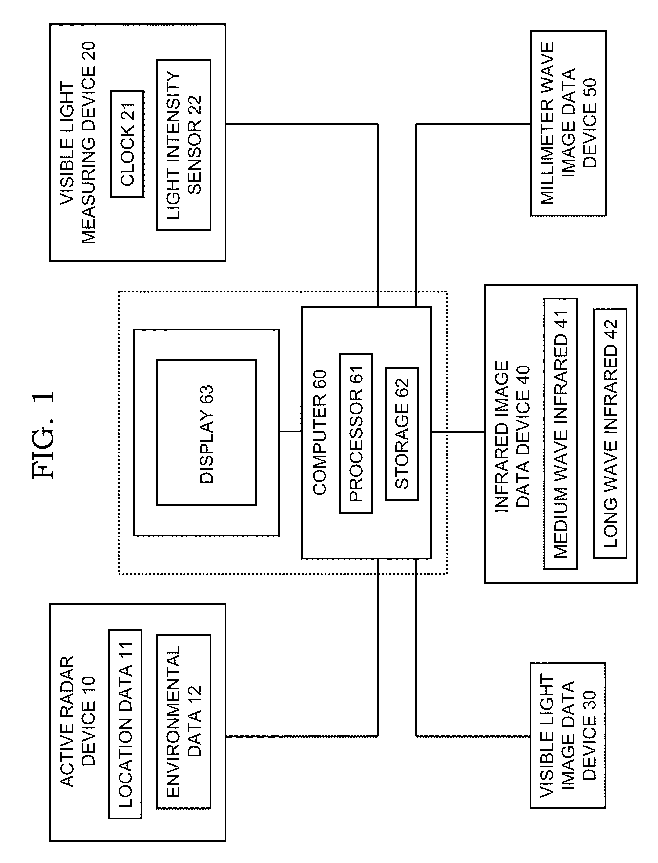
[0041]Referring now to FIG. 1 through FIG. 4, computer 60 includes a processor 61 and memory / storage 62 (typically, both volatile and non-volatile) for holding and processing data and for running compute software, embodied in computer code. Computer 60 has resident in its memory / storage 62 an embodiment of an image fusion computer program in accordance with the present invention. Connected to computer 60 is display 63, on which are displayed the composite multispectral images generated by computer 60 in accordance with typical practice of the present invention.

[0042]The active radar device 10 includes a detection-and-tracking-type radar component 11 and a weather-type radar component 12. Light measurement device 20 is any suitable visual light-measuring means, such as including a clock (timekeeping instrument) 21 and / or a light meter (light sensing device) 22. The passive non-radar electromagnetic sensors include a visible light image data device 30, an infrared image data device 40...


PUM


Abstract

Typical inventive practice provides for electronic communication of a computer with a display, an active radar device (for transmitting target-location data and environmental data), a light measurement device (for transmitting visual light data), and passive imaging devices covering bands in the visual, infrared (MWIR and / or LWIR), and millimeter wave regions of the electromagnetic spectrum. Inventive software in the computer's memory establishes “operational modes.” Each operational mode is defined at least by a predominant environmental (obscuration and lighting) character, ascribes “modal indices” to individual imaging devices, and carries its own multispectral image fusion algorithm (which, pursuant to the ascribed modal indices, attributes weights to the imaging data from the respective imaging devices). The inventive software aims the imaging devices toward the target, selects an operational mode (based on the environmental data), and executes the image fusion algorithm associated with the selected operational mode so that a fused multispectral image is displayed.

Description

BACKGROUND OF THE INVENTION[0001]The present invention relates to electromagnetic imaging, more particularly to methods and devices involving fusion of images from plural electromagnetic spectral band regions.[0002]Traditional approaches to navigating waters or detecting threats under low-light conditions have involved radar systems, infrared (IR) devices, or electro-optic / light-intensification (EO / LI) devices. Radar devices used for navigation / detection purposes are usually “active” in the sense that they transmit electromagnetic radiation—more specifically, radio signals—in order to receive reflected radio signals that are informative as to existence of targets (objects) and their whereabouts. IR devices and EO / LI devices used for such purposes are “passive” in the sense that they do not transmit electromagnetic radiation, but instead receive naturally occurring electromagnetic signals that are emanated or reflected by targets.[0003]In the electromagnetic spectrum, the IR region i...

Claims


Application Information

Patent Timeline
Patent Type & Authority Patents(United States)
IPC IPC(8): G01S13/00
CPCG01S13/89G01S13/867
Inventor SMITH, JR., JERRY ROSSONKRYCIA, JOSEPH R.
Owner NAVY THE UNITED STATES OF AMERICA SEC OF THE
Why Eureka
Try Eureka