
Probabilistic gain-sensing ringing feedback detector

Active Publication Date: 2012-01-24
CLEARONCE COMM INC
View PDF2 Cites 10 Cited by
  • Summary
  • Abstract
  • Description
  • Claims
  • Application Information

AI Technical Summary

Benefits of technology

[0016]Disclosed herein are detectors of audio ringing feedback, that is decaying feedback with a gain of less than one, those detectors utilizing a repeated gain measurement that applied to a range of gain values characteristic of ringing-type feedback. Those gain measurements, while in the range, increase a probability measurement of feedback. When the probability of feedback reaches a threshold, a detection of feedback is made and feedback countermeasures, such as the application of a notch filter, may be applied. Optionally, the audio gain around likely frequencies of feedback may be enhanced for a time to increase the resolution of identification of a feedback frequency, which may be identified through an interpolative method. Repeated gain measurements may also identify building-type feedback. A ringing detector may include more than one range of detection, for example for building, strong-ringing and weak-ringing feedback.

Problems solved by technology

Feedback in public address systems is a common problem.
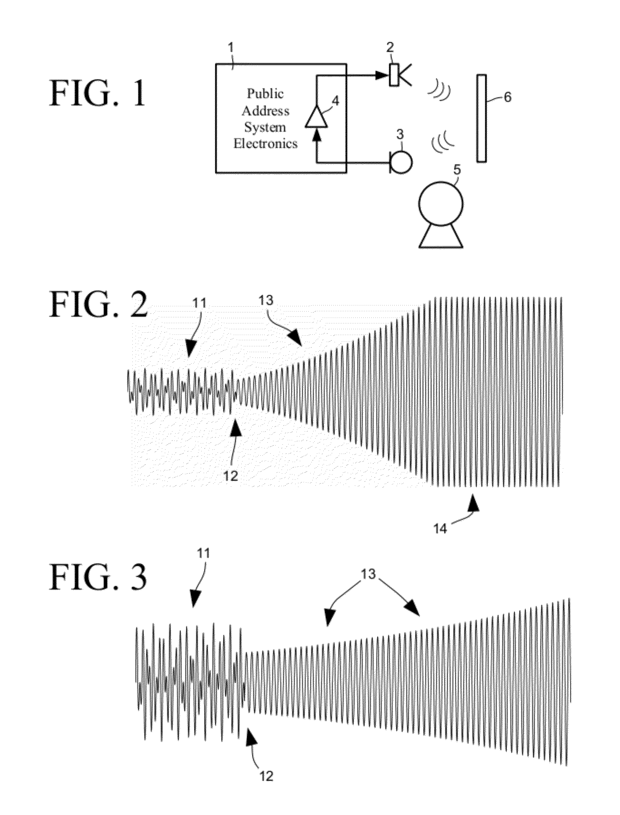
However, there may be one or more objects 6 that reflect speaker-produced sound to the microphone 3 that may cause difficulty.
However, all of these systems must wait for a period of howling to occur, and are not capable of proactively suppressing feedback.
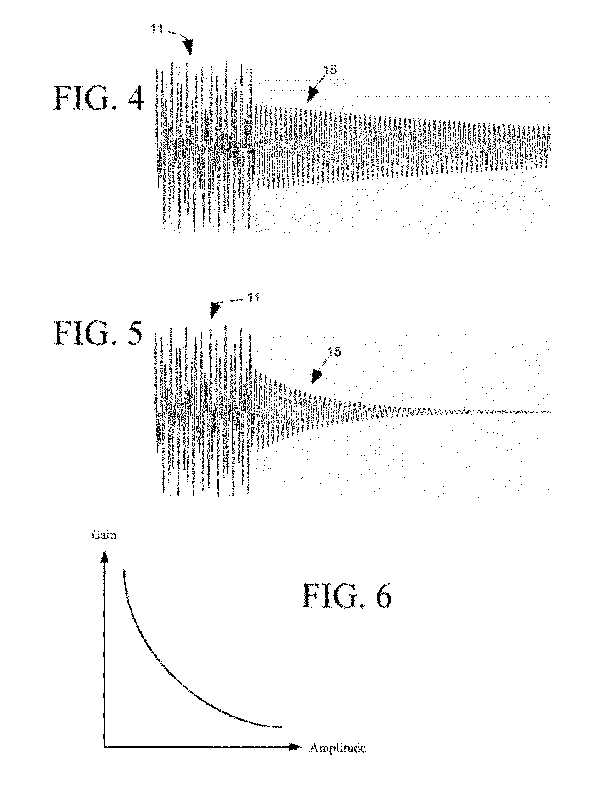
The prior remedial measures for howling are not effective to ringing, generally because the amplitude of the ringing is less than the amplitude of participant speech and is more difficult to detect.
Weak-ringing such as that shown in FIG. 5 may decay more rapidly, but although might not be immediately identifiable by a person may also be a nuisance; muddying speech and fatiguing the ears of listeners.

Method used


Image

  • Probabilistic gain-sensing ringing feedback detector
  • Probabilistic gain-sensing ringing feedback detector
  • Probabilistic gain-sensing ringing feedback detector

Examples


Embodiment Construction

[0033]Prior methods to howling and feedback are more or less remedial in nature; they wait for an objectionable feedback event to occur and then take remedial measures. As will be seen, the systems and methods described herein are more proactive than these prior methods, in that countermeasures to feedback can be employed before a feedback event causes an interruption to meeting participants in many cases.

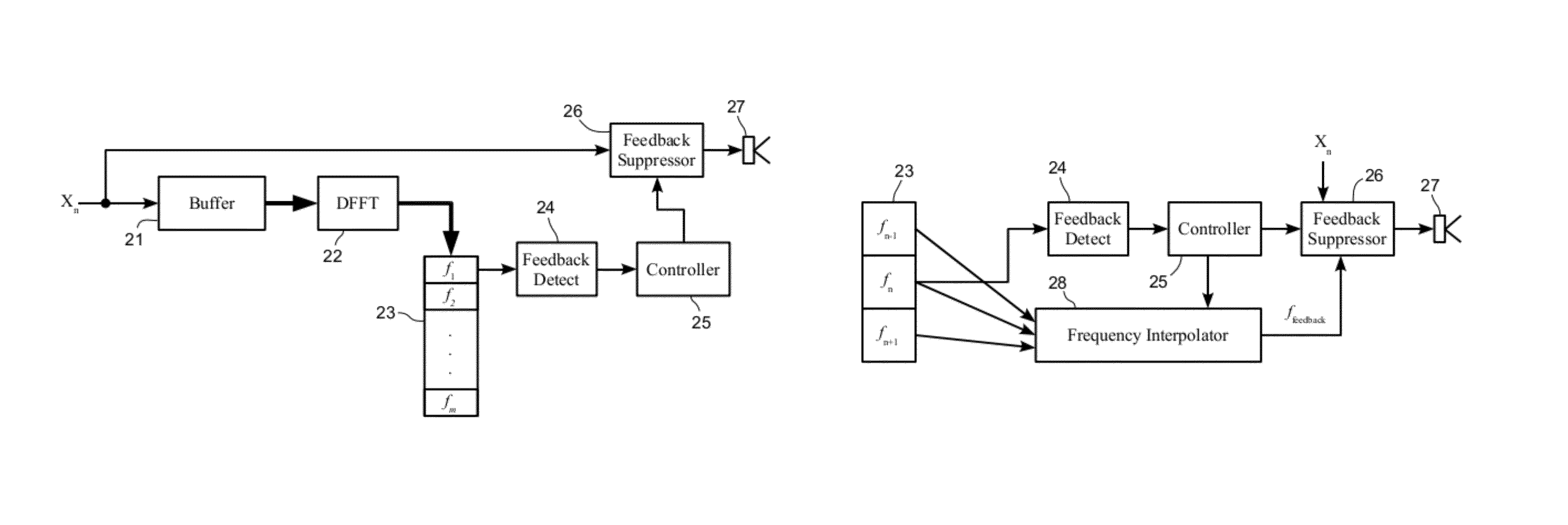
[0034]FIG. 7 depicts the elements of an exemplary generic feedback suppressor for the purposes of this discussion, which are a buffer 21 which is fed a series of samples Xn representing the input at one or more microphones. It is to be understood that samples Xn might come directly from a microphone, but those samples could also come from a signal delivered to a speaker or an intermediate signal, so long as those signals are from a microphone in the sense that a microphone is included in the signal path as an input. It is also to be understood that a microphone may be a microphone ...


PUM


Abstract

Disclosed herein are detectors of audio ringing feedback, that is decaying feedback with a gain of less than one, those detectors utilizing a repeated gain measurement that applied to a range of gain values characteristic of ringing-type feedback. Those gain measurements, while in the range, increase a probability measurement of feedback. When the probability of feedback reaches a threshold, a detection of feedback is made and feedback countermeasures, such as the application of a notch filter, may be applied. Optionally, the audio gain around likely frequencies of feedback may be enhanced for a time to increase the resolution of identification of a feedback frequency, which may be identified through an interpolative method. Repeated gain measurements may also identify building-type feedback. A ringing detector may include more than one range of detection, for example for building, strong-ringing and weak-ringing feedback.

Description

CROSS REFERENCE TO RELATED APPLICATIONS[0001]The following applications share a common specification: U.S. application Ser. No. 12 / 247,747 (date filed 8 Oct. 2008), U.S. application Ser. No. 12 / 247,757 (date filed 8 Oct. 2008), and U.S. application Ser. No. 12 / 247,768 (date filed 8 Oct. 2008).BACKGROUND[0002]The claimed systems and methods relate generally to audio feedback detectors and feedback interrupters, and more particularly to audio amplification systems that include a feedback loop and a detector of non-building, or ringing, feedback, those systems including public address systems and other electronic devices such as hearing aids.[0003]Feedback in public address systems is a common problem. For background and referring to FIG. 1, a public address system includes a microphone 3 for picking up the speech of a participant 5 and a speaker 2 for broadcasting that speech into a room where others may hear. A public address system also includes electronics 1 that may include severa...

Claims


Application Information

Patent Timeline
IPC IPC(8): H04B15/00
CPCH04R3/02H04R27/00H04R29/007H04R2430/03
Inventor PANDEY, ASHUTOSHLAMBERT, DAVID
Owner CLEARONCE COMM INC
Learn More