
Brittle workpiece splitting system and brittle workpiece splitting method

a workpiece and splitting system technology, applied in glass making apparatus, manufacturing tools, transportation and packaging, etc., can solve the problems of high cost, complex apparatus, and inability to accurately extend linearly, and achieve high processing quality, high rigidity of the edge damper, and fast cutting

Inactive Publication Date: 2012-01-31
SHIBAURA MECHATRONICS CORP +1
View PDF16 Cites 57 Cited by
  • Summary
  • Abstract
  • Description
  • Claims
  • Application Information

AI Technical Summary

Benefits of technology

Enables quick and high-quality cutting of edge parts with reduced deviations, eliminating the need for expensive control systems and optical systems, resulting in a simple and cost-effective splitting process.

Problems solved by technology

The foregoing related art splitting methods need an expensive control system and an optical system to carry out complicated control operations for controlling irradiation with the laser beam and spraying the coolant on the substrate.
Consequently, the prior art splitting methods need an expensive, complex apparatus.
However, a problem that a crack extends along a meandering line arises when this related art splitting method is applied to a trimming process for cutting off an edge part of a substrate and the splitting method is unable to cause a crack to extend accurately linearly.

Method used


Image

  • Brittle workpiece splitting system and brittle workpiece splitting method
  • Brittle workpiece splitting system and brittle workpiece splitting method
  • Brittle workpiece splitting system and brittle workpiece splitting method

Examples


Embodiment Construction

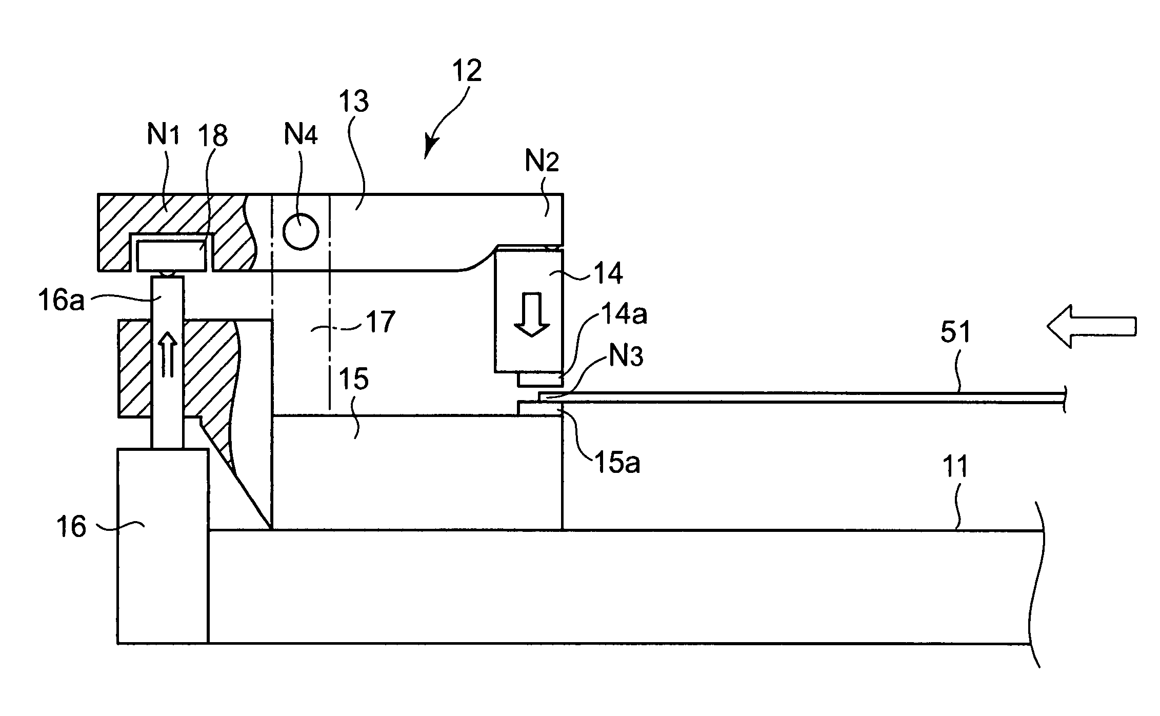
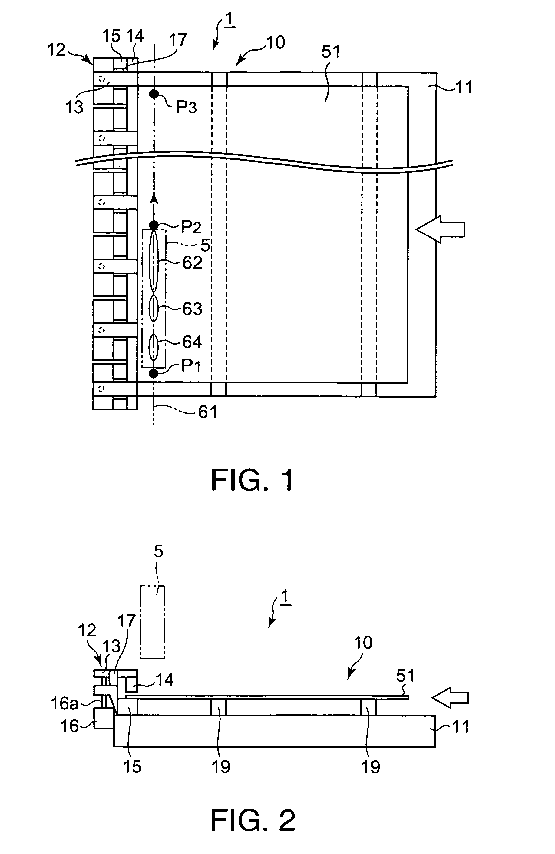
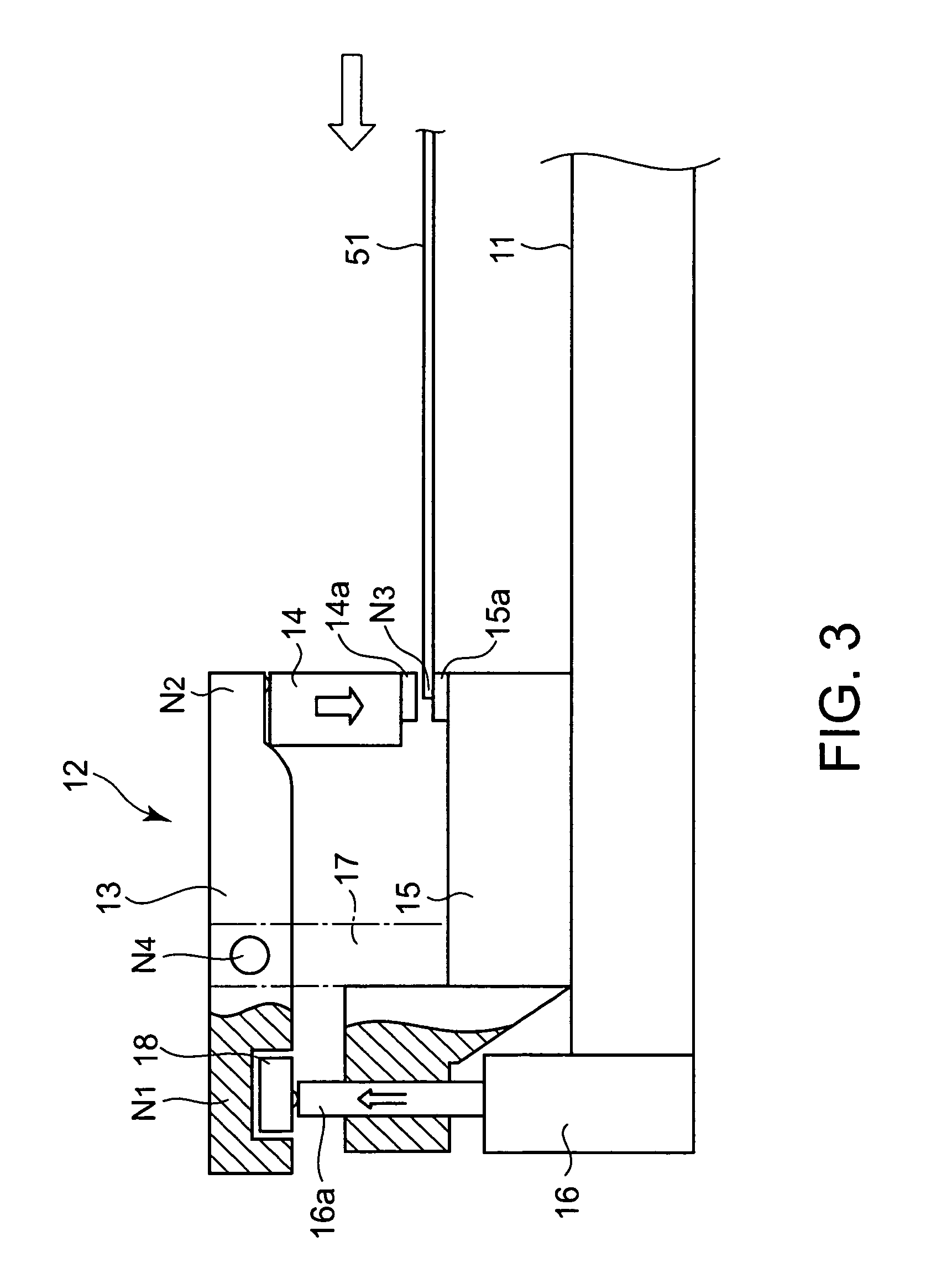
[0035]A brittle workpiece splitting system in a preferred embodiment of the present invention will be described with reference to the accompanying drawings.

[0036]The constitution of the brittle workpiece splitting system in a preferred embodiment of the present invention will be described with reference to FIGS. 1 to 4.

[0037]Referring to FIGS. 1 and 2, a brittle workpiece splitting system 1 carries out a splitting process of locally heating a substrate 51 made of a brittle material, such as glass, to cause a crack in the substrate 51 by thermal stress induced in the substrate 51. The brittle workpiece splitting system 1 has a substrate holding mechanism 10 for holding the substrate 51, and a processing unit 5 for processing the substrate 51 by the splitting process. It is supposed herein that the substrate 51 to be processed by the brittle workpiece splitting system 1 is a glass substrate.

[0038]The substrate holding mechanism 10 has an edge damper 12 adapted to clamp an edge part of...


PUM

PropertyMeasurementUnit
Young's modulusaaaaaaaaaa
widthaaaaaaaaaa
thicknessaaaaaaaaaa

Abstract

The brittle workpiece splitting system 1 includes a substrate holding mechanism 10 for holding a substrate 51, and a processing unit 5 for splitting the substrate 51 held by the substrate holding mechanism 10 by a splitting process. The substrate holding mechanism 10 has an edge damper 12 adapted to clamp an edge part of the substrate 51 from the sides of the opposite surfaces of the edge part, and support members 19 for supporting the substrate 51 thereon at a predetermined height. The support members 19 are disposed on the side opposite the side of the edge damper 12 with respect to the intended split line 61 parallel to the edge part of the substrate 51. The edge damper 12 has an edge holder 15 on which the substrate 51 is seated, and a pressure bar 14 for pressing the substrate 51 against the edge holder 15 to hold the substrate 51 between the edge holder 15 and the pressure bar 14. Resin members 14a and 15a made of an elastic material having comparatively high rigidity are attached to parts, to be brought into contact with the substrate 51, of the pressure bar 14 and the edge holder 15, respectively. The support members 19 are made of a low-friction material to permit the horizontal movement of the substrate 51 during the splitting process.

Description

BACKGROUND OF THE INVENTION[0001]1. Field of the Invention[0002]The present invention relates to a brittle workpiece splitting system for splitting a substrate made of a hard, brittle material by locally heating the substrate to cause a crack in the substrate. More particularly, the present invention relates to a brittle workpiece splitting system capable of quickly achieving a splitting process for cutting off an edge part of a substrate in a high processing quality, and to a brittle workpiece splitting method to be carried out by the brittle workpiece splitting system. This patent application is based on application Nos. 2004-296215 and 2005-249928 the content of which are incorporated hereinto by reference.[0003]2. Description of the Related Art[0004]A conventional splitting method of splitting a planar substrate, such as a glass substrate or the like for a liquid crystal display panel or a plasma display panel, locally heats the substrate and cools the locally heated substrate. ...

Claims


Application Information

Patent Timeline
Patent Type & Authority Patents(United States)
IPC IPC(8): B26D7/10B23K26/14B26F3/00C03B31/00
CPCC03B33/033C03B33/093Y10T225/321Y10T225/304Y10T83/041Y10T225/12
Inventor HAYASHI, MASAKAZUNAKATA, SHINJIYAHAGI, SUSUMU
Owner SHIBAURA MECHATRONICS CORP
Learn More