Methods and apparatus for optical transmission of digital signals

a digital signal and optical transmission technology, applied in the field of optical communication, can solve the problems of suppression of the amplitude of the signal (or fading) over particular, possible additional signal distortion sources of signals, and introduction of distortion in the transmitted optical signal, so as to reduce the reliance on inherent limitations, and improve the effect of optical power budg

Active Publication Date: 2012-01-31
MONASH UNIV
View PDF4 Cites 14 Cited by
  • Summary
  • Abstract
  • Description
  • Claims
  • Application Information

AI Technical Summary

Benefits of technology

[0023]Accordingly, the inventive method involves transmission of optical signals that may be asymmetrically amplitude limited and more particularly may be intensity-modulated signals that are amplitude limited at a zero optical output power level. The method thereby enables bipolar signals to be transmitted over a unipolar optical channel simply by allowing either the positive or negative amplitude excursions of the transmitted signals to be limited for transmission over the optical channel. This reduces or eliminates the need to apply a high optical bias level at the transmitter, thereby improving optical power efficiency and enabling output power levels to be maintained below applicable safe levels.
[0060]means for performing a frequency domain equalisation of the received electrical signal to mitigate the effect of dispersion of the optical channel on the transmitted optical signal; and

Problems solved by technology

However, optical transmission paths, whether over single-mode or multi-mode optical fibres, or through free space, may introduce distortion in the transmitted optical signals.
Furthermore, the devices used for the transmission and reception of optical signals are possible additional sources of signal distortion.
A common form of distortion is a frequency-dependent variation in the response of the communications channel, which may result in suppression of the amplitude of the signal (or fading) over particular frequency ranges and / or at specific frequencies, as well as variations in delay, or phase, of the received signal as a function of frequency.
Such distortion may result from the frequency characteristics of the various electronic and optical devices used in the transmission system, as well as the characteristics of the optical transmission path itself.
Accordingly, different components of the received optical signal experience different transmission delays, resulting in a time spread in the received optical signal which is one form of dispersion.
Accordingly, the components of the transmitted signal coupled into different transverse modes experience differing transmission delays along the multi-mode fibre, again resulting in dispersion of the received signal.
The dispersion resulting from multi-path propagation in free space optical transmission systems, and from modal dispersion within multi-mode fibres, may be either relatively static or time-varying, and can result in corresponding static or time-varying frequency fading in the received signal.
Both of these dispersion mechanisms, amongst others including various nonlinear processes, may result in spreading of transmitted pulses.
Additionally, all optical transmission channels will exhibit other forms of frequency-dependent distortion resulting from the characteristics of the transmitting and receiving electronic and opto-electronic components.
However, the use of such modulation schemes over optical channels has, to date, proven problematic.
This is inherently a unipolar modulation system, since negative values of power or intensity are not physically meaningful, and cannot be generated.
Past efforts to overcome the limitations inherent in unipolar intensity modulation have proven largely ineffective or impractical.
However, this is highly inefficient in its utilisation of the available optical transmission power, particularly in the case of multi-carrier modulation schemes which may generate signals having a very large peak-to-average power ratio, such that the peak excursions are much larger than the signal average value.
While optical power inefficiency may be an issue in all types of optical transmission systems, an additional problem in free space systems is that the required optical output power may exceed eye-safe levels.
However, all of these methods result in additional cost and complexity, while some require the use of coherent optical channels, and as such they are generally too expensive or otherwise impractical for many relevant applications.

Method used


Image

  • Methods and apparatus for optical transmission of digital signals
  • Methods and apparatus for optical transmission of digital signals
  • Methods and apparatus for optical transmission of digital signals

Examples


Embodiment Construction

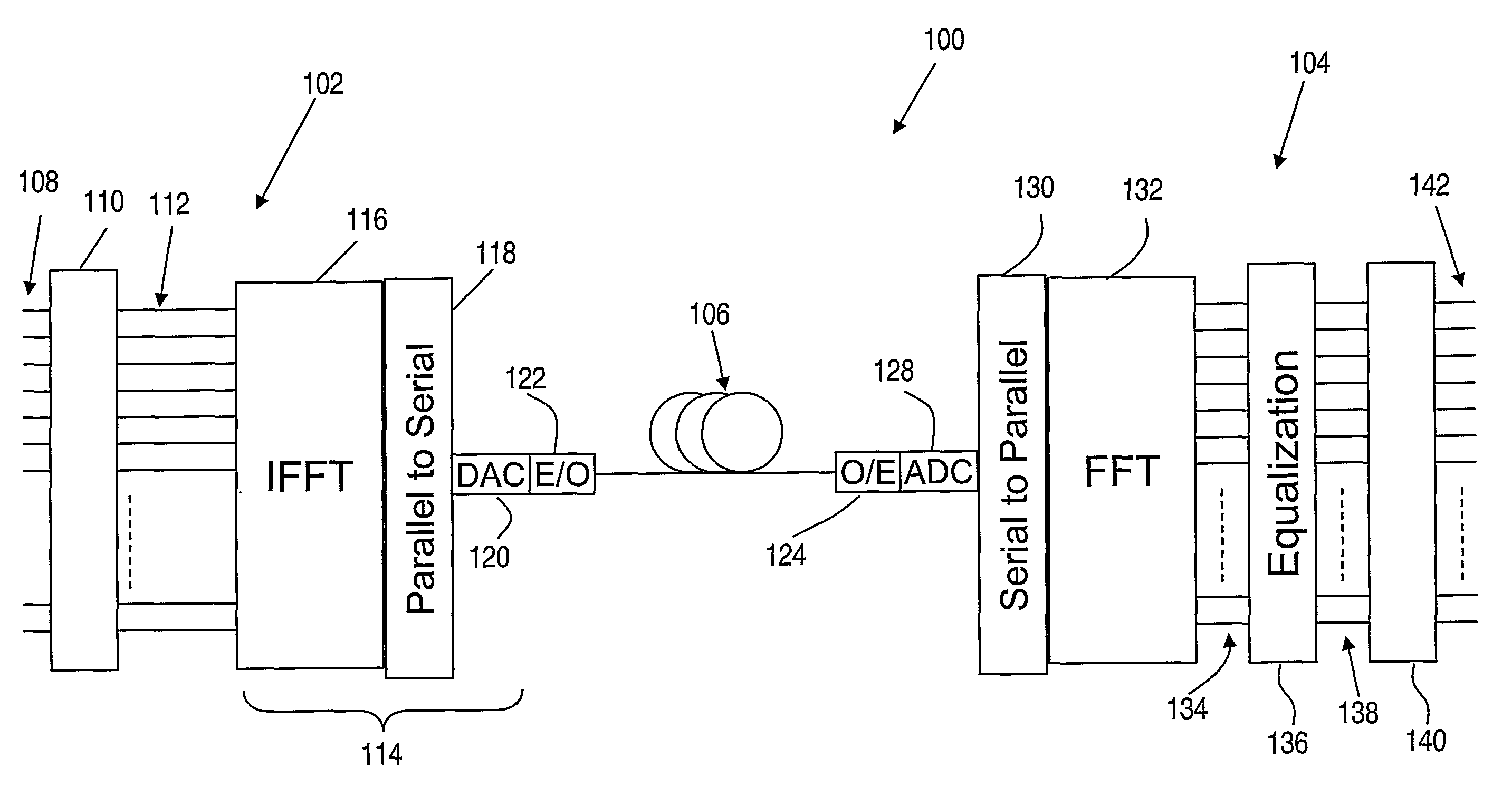
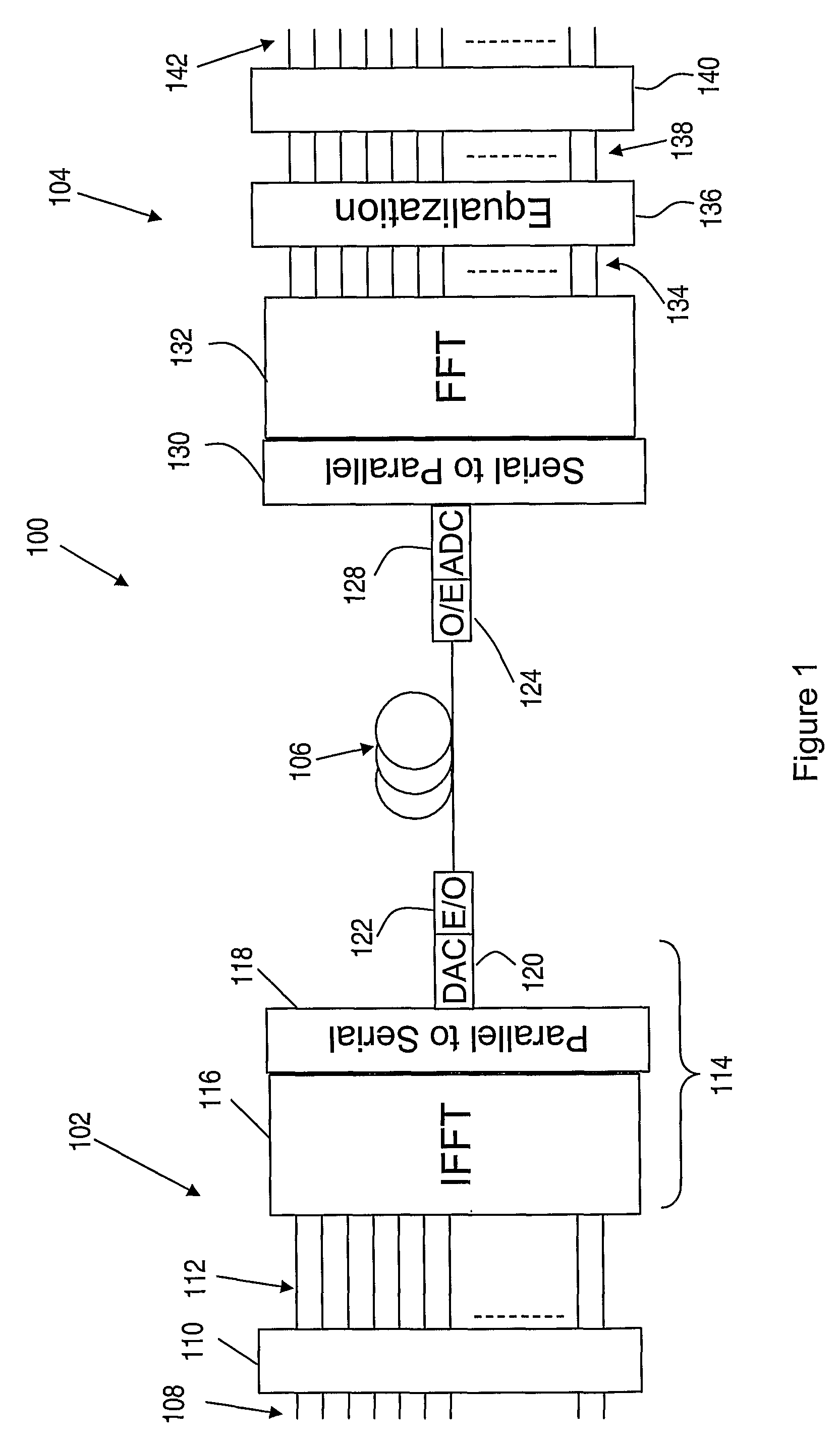
[0078]Turning first to FIG. 1, there is shown schematically a system for communicating digital information over an optical channel according to a preferred embodiment of the present invention. While the invention is exemplified herein by the system 100, which employs orthogonal frequency division multiplexing (OFDM) in encoding and modulating signals for transmission over an optical channel, it is to be understood that the invention is not limited to this particular embodiment. Rather, embodiments of the invention are characterised generally by coding of digital information in blocks, the optional addition of a guard time or cyclic prefix at the transmitter, and equalisation of the received signal in the frequency domain after transmission over the optical channel. While OFDM provides one advantageous means for implementing these functions, the description of preferred embodiments by reference to an OFDM implementation will be understood to be exemplary only, and not limiting of the...


PUM


Abstract

A method of communicating digital information over a dispersive optical channel includes encoding the digital information into a plurality of data blocks, each of which includes a number of bits of the information. A time-varying electrical signal is generated which corresponds with each of said data blocks. The time-varying electrical signal is applied to an optical transmitter (122) to generate an optical signal which includes an asymmetrically amplitude limited transmitted signal modulated onto an optical carrier. The optical signal is then transmitted over the dispersive optical channel (106). At a receiving apparatus (104) the optical signal is detected to produce an electrical signal which corresponds with the asymmetrically amplitude limited transmitted signal. A frequency domain equalization of the electrical signal mitigates the effect of dispersion of the optical channel (106) on the transmitted optical signal, and the equalized signal is decoded to recover the encoded data blocks and the corresponding transmitted digital information. The method enables bipolar signals to be transmitted over a dispersive unipolar optical channel, and reduces or eliminates the need to apply a high optical bias level at the transmitter, thereby improving optical power efficiency and enabling output power levels to be maintained below applicable safe levels, while simultaneously enabling the effects of channel dispersion to be substantially mitigated.

Description

CROSS REFERENCE TO RELATED APPLICATIONS[0001]This application is the US national phase of PCT Application No. PCT / AU2006 / 001282, filed Sep. 1, 2006, which was based on Australian Application No. 2005904833, filed Sep. 2, 2005.FIELD OF THE INVENTION[0002]The present invention relates generally to optical communications, and more particularly to methods and apparatus, for modulation and transmission of digital signals, which are particularly advantageous in communications systems that include dispersive optical paths.BACKGROUND OF THE INVENTION[0003]Optical transmission, in which an information signal is modulated onto an optical carrier, is widely employed in modern communications systems. For example, long-haul transmission networks employ single-mode optical fibres for the transmission of digital information at very high bit rates, using one or more optical carriers, or wavelengths, over each fibre. Furthermore, optical transmission over shorter distances, and at lower bit rates, s...

Claims


Application Information

Patent Timeline
Patent Type & Authority Patents(United States)
IPC IPC(8): H04B10/12H04J14/00
CPCH04B10/25133H04B10/548H04B10/25H04B10/516H04B10/50
Inventor ARMSTRONG, JEANLOWERY, ARTHUR JAMES
Owner MONASH UNIV
Why Eureka
Try Eureka