
Method of automatically controlling a respiration system and a corresponding respirator

a technology of respiration system and respirator, which is applied in the direction of respiratory organ evaluation, operating means/releasing devices for valves, diagnostic recording/measuring, etc., can solve the problems of large errors in determining the technical parameter of breathing, decrease of risk of runaway, and inability to guarantee the validity of measurement. , to achieve the effect of convenient for patients

Active Publication Date: 2012-02-07
DRAGERWERK AG
View PDF10 Cites 8 Cited by
  • Summary
  • Abstract
  • Description
  • Claims
  • Application Information

AI Technical Summary

Benefits of technology

The present invention provides a method for automatically controlling a respiration system for proportional assist ventilation that is convenient for patients and operates accurately over the long term. The method involves recording the breathing activity of the patient using surface electrodes or sensors and analyzing the recorded data to determine the breathing cycle and the mechanical parameters of the patient's lungs. The resulting information is used to set the degree of assist, which is the pressure that helps the patient breathe. The method is non-invasive and can be used with different types of sensors. It reduces the risk of run-aways and ensures a constant level of assist during the breathing cycle.

Problems solved by technology

However, a sufficiently accurate estimated value must be available for this for the actual resistance® and elastance (E), because instabilities (so-called run-aways) and possible damage to the lungs due to barotrauma may otherwise develop.
The special difficulty is due to the fact that the patient's spontaneous breathing activities may cause great errors in determining the breathing technical parameter.
However, it is not guaranteed that the patient is in an undisturbed phase of the breathing cycle at the time of the maneuver, and the validity of the measurement is therefore not guaranteed; it also cannot be demonstrated later.
As a result, the risk of run-away decreases.
Termination of the inspiration (“cycling off”) is likewise unproblematic.
One drawback of the NAVA method is that an invasive gastric probe is necessary.
Patients who would especially benefit from the use of NAVA methods (e.g., patients with COPD subjected to long-term noninvasive respiration, i.e., respiration with a mask), will dislike accepting such a permanent solution.
Furthermore, it is not possible to make a distinction between a situation in which the EAdi signal is compromised for technical reasons inherent in the device (e.g., due to interference signals or faulty coupling between the signal source and the electrodes) and a situation in which the respiratory drive decreases.
If the coupling between the signal source and the electrodes changes—e.g., deteriorates—in this equilibrium, the tidal volume is reduced, the drive and the respiratory effort gradually increase, but the measured EAdi signal decreases, which means that the percentage of the work of breathing performed by the patient increases in an undesired manner.
This method is disadvantageous in the case that frequently occurs in reality, in which the signal properties (especially the amplitude) of the measured EAdi signal change, e.g., decrease due to a change in the coupling between the electrodes and the signal source (caused, e.g., by repositioning of the patient).
The controller of the “closed-loop” system would consequently erroneously reduce the assist, because the neuroventilatory efficiency has seemingly increased.

Method used


Image

  • Method of automatically controlling a respiration system and a corresponding respirator
  • Method of automatically controlling a respiration system and a corresponding respirator
  • Method of automatically controlling a respiration system and a corresponding respirator

Examples


Embodiment Construction

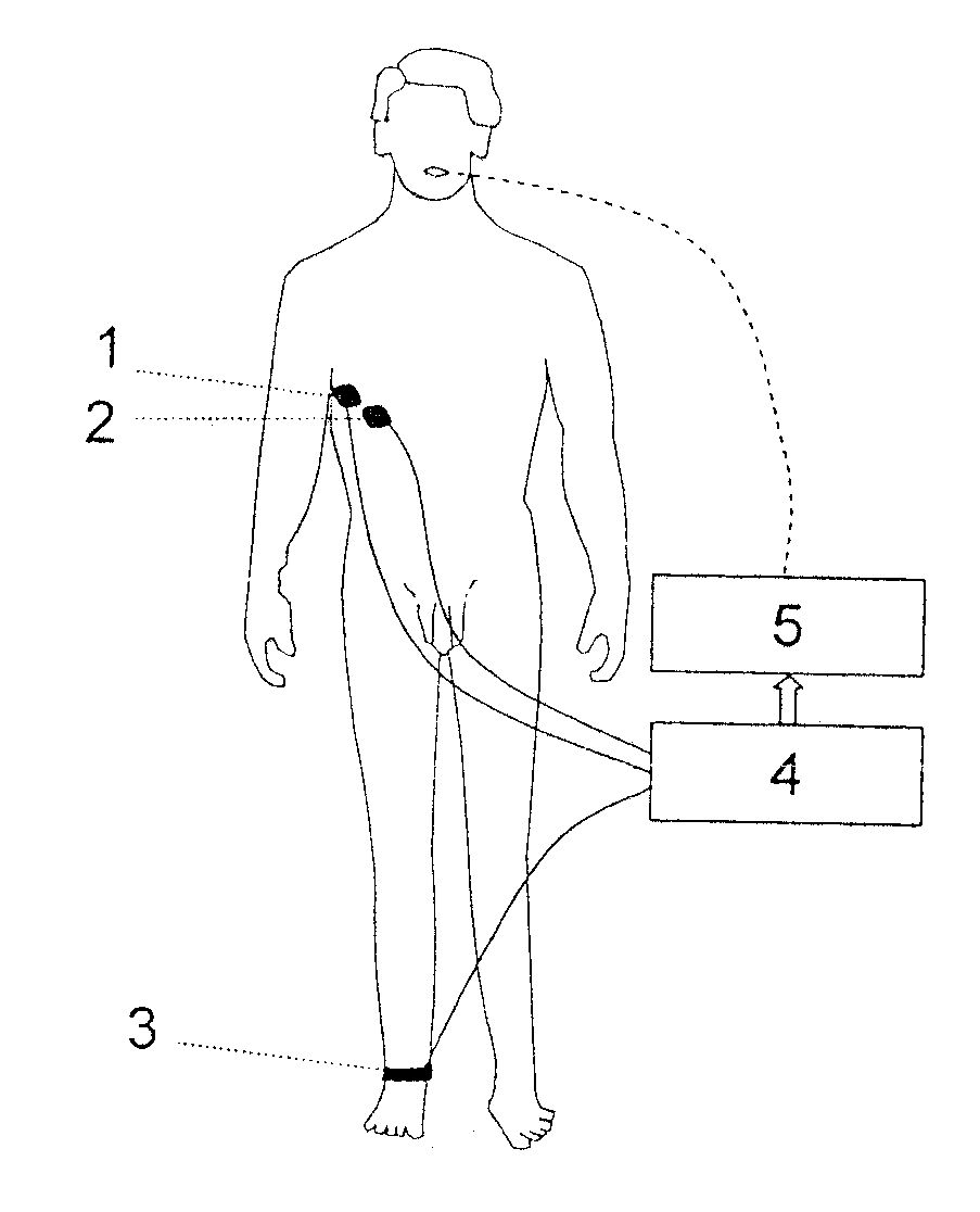
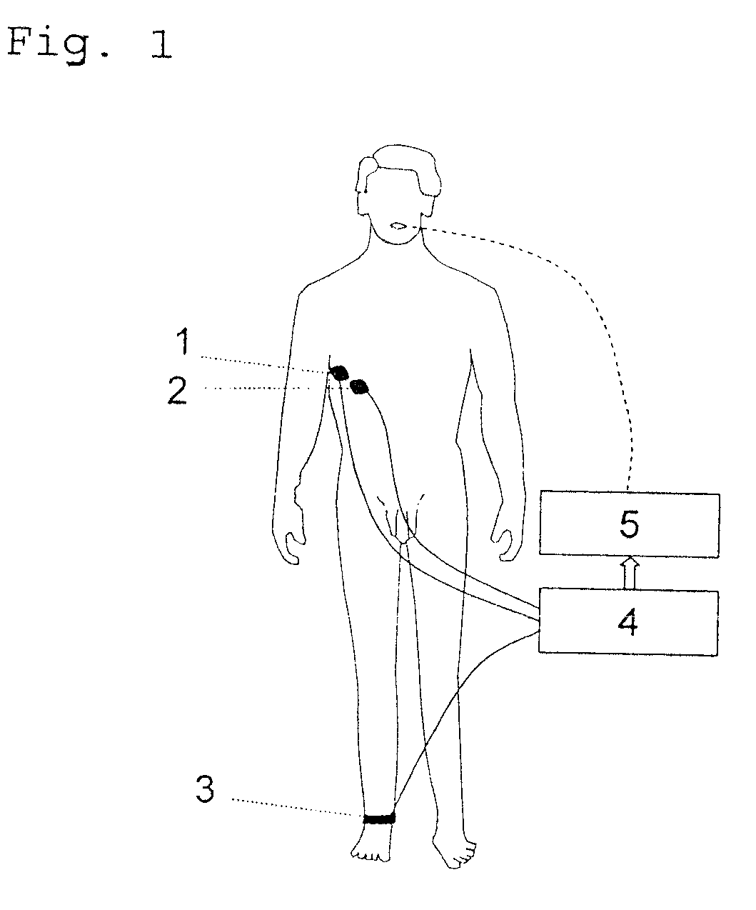
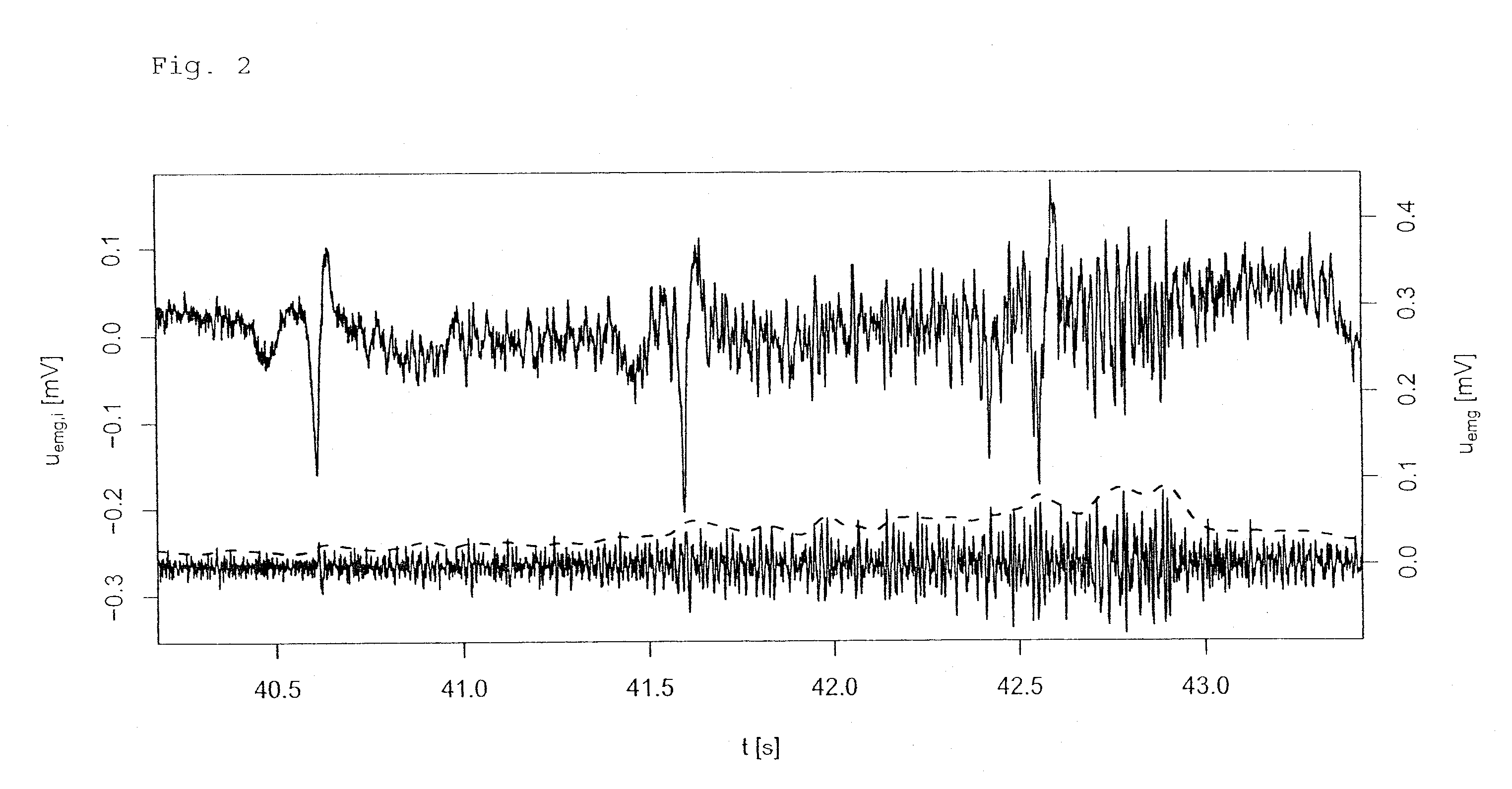
[0039]Referring to the drawings in particular, according to the present invention, the breathing activity signal can be recorded alternatively by electromyography or mechanomyography, both methods providing a signal representing the muscular exertion; a signal representing the electric excitation of the muscle in the first case and a signal representing the mechanical vibrations of the muscle in the second case. Reference will be made below mostly to the electromyographic alternative, and this should be understood such that it would alternatively also be possible to use mechanomyographic signals.

[0040]In an advantageous embodiment, the value of the breathing activity signal uemg(t) is checked continuously in the control unit to determine whether the signal is below another threshold value criterion, and a passive period of the breathing cycle is established for the duration of the period during which said signal is below said threshold value, and the other lung mechanical parameter ...


PUM


Abstract

A method of automatically controlling a respiration system for proportional assist ventilation with a control device and with a ventilator. An electrical signal is recorded by electromyography with electrodes on the chest in order to obtain a signal uemg(t) representing the breathing activity. The respiratory muscle pressure pmus(t) is determined by calculating it in the control unit from measured values for the airway pressure and the volume flow Flow(t) as well as the patient's lung mechanical parameters. The breathing activity signal uemg(t) is transformed by means of a preset transformation rule into a pressure signal pemg(uemg)(t)) such that the mean deviation of the resulting transformed pressure signal pemg(t) from the respiratory muscle pressure pmus(t) is minimized. The respiratory effort pressure ppat(t) is determined as a weighted mean according to ppat(t)=a·pmus(t)+(1−a)·pemg(t), where a is a parameter selected under the boundary condition 0≦a≦1.

Description

CROSS REFERENCE TO RELATED APPLICATIONS[0001]This application claims the benefit of priority under 35 U.S.C. §119 of German Patent Application DE 10 2007 062 214.9 filed Dec. 21, 2007, the entire contents of which are incorporated herein by reference.FIELD OF THE INVENTION[0002]The present invention pertains to a method and a device for automatically controlling a respiration system (also known as ventilation system) for proportional assist ventilation, with a control means and with a ventilator, which delivers a breathing gas with a pressure preset by the control unit.BACKGROUND OF THE INVENTION[0003]Methods that assist the patient proportionally to his or her own respiratory effort and relieve the patient of the increased work of breathing in order to thus prevent exhaustion of the respiratory muscles and the so-called respiratory failure have been developed in recent years for respirating spontaneously breathing patients. Compared to conventional forms of respiration, the form of...

Claims


Application Information

Patent Timeline
Patent Type & Authority Patents(United States)
IPC IPC(8): F16K31/02
CPCA61B5/0488A61B5/08A61M16/0051A61B5/037A61B5/085A61B5/087A61B5/224A61B5/7203A61M2016/0027A61M2016/0036A61M2230/60A61M2230/63A61B5/7239A61M16/026A61B5/389A61M16/00A61B5/0816
Inventor EGER, MARCUS
Owner DRAGERWERK AG
Learn More