Exercise device with varied gait movements

a technology of exercise device and gait movement, applied in the field of exercise equipment, can solve the problems of reducing muscle tissue, affecting the movement of the foot, and affecting the movement of the foot, and achieve the effect of limiting the vertical displacement of the foot suppor

Active Publication Date: 2012-02-07
EXERCITING
View PDF15 Cites 20 Cited by
  • Summary
  • Abstract
  • Description
  • Claims
  • Application Information

AI Technical Summary

Benefits of technology

[0009]The support system may be comprised of one or more belts, each movably coupled to the frame by at least two pulleys. The belt may include an upper run positioned adjacent to a lower portion of the foot support and adapted for contact with the upper run, thereby the belt may limit the vertical displacement of the foot support. The support system may be comprised of a belt take-up coupled to the frame, the belt take-up may be biased to provide tension in the belt. The support system may also include a belt drive, such as a motor or other power device, operationally coupled to the belt to enable continuous rotation of one or more of the pulleys, thereby allowing continuous movement of the belt in the absence of power input from a user.

Problems solved by technology

Without proper exercise, muscle tissue decreases, the mineral density of bones decline and people tend toward storing more fat weight.
The ground pounding action of running can cause joint issues in some people.
Weather and personal safety restrict some individuals from performing this activity as often as they would like, as running in bad weather or a bad neighborhood can result in more serious problems than heart disease.
Indoor running and walking can be accomplished by use of a treadmill, but again, the pounding action of the foot on the tread may lead to joint overuse injuries.
Any slight variation between the user's natural gait and the machine's predetermined gait may cause an imbalance in joint loading, as well as muscular development of the limbs being used.

Method used


Image

  • Exercise device with varied gait movements
  • Exercise device with varied gait movements
  • Exercise device with varied gait movements

Examples


Embodiment Construction

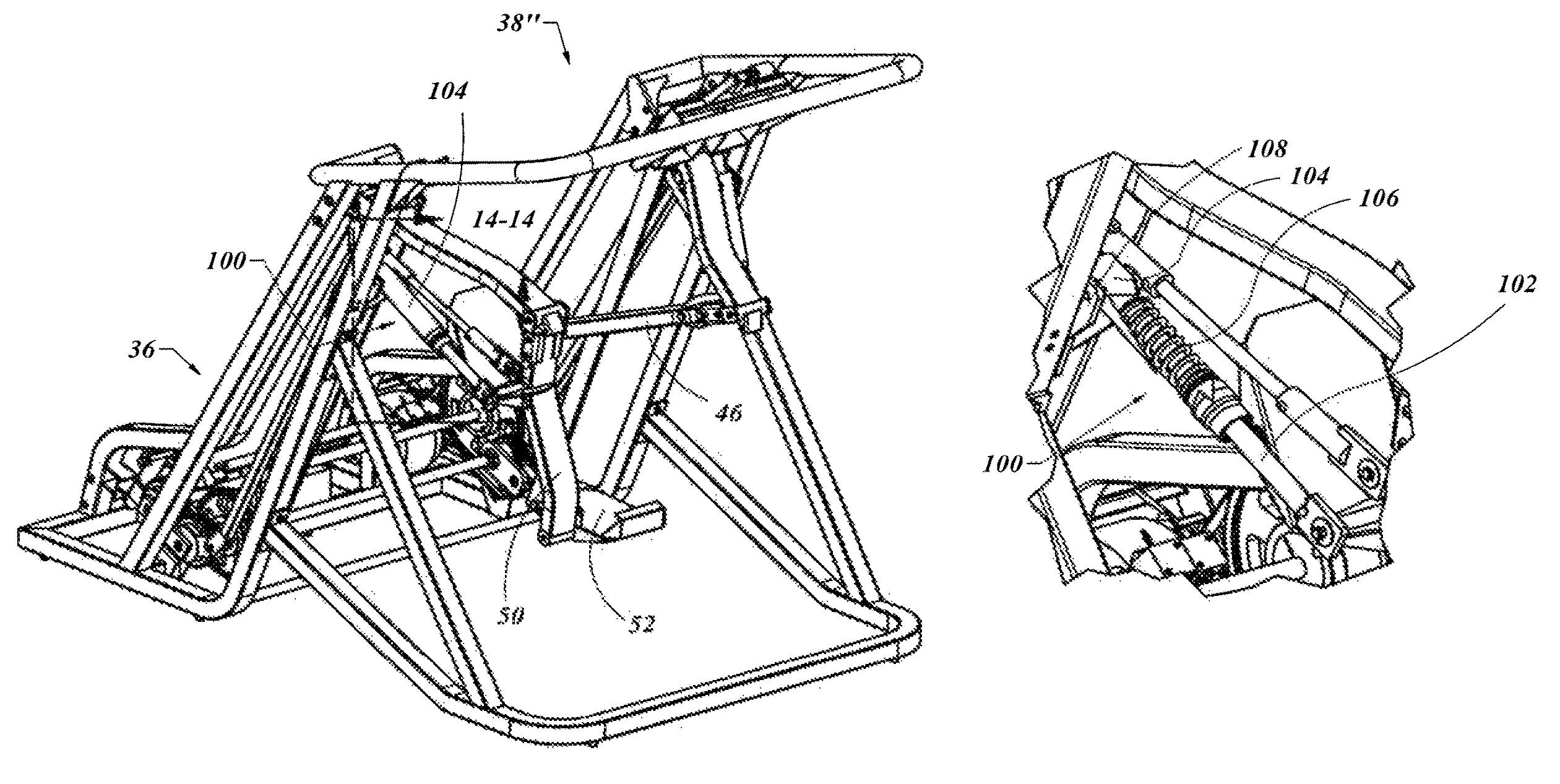
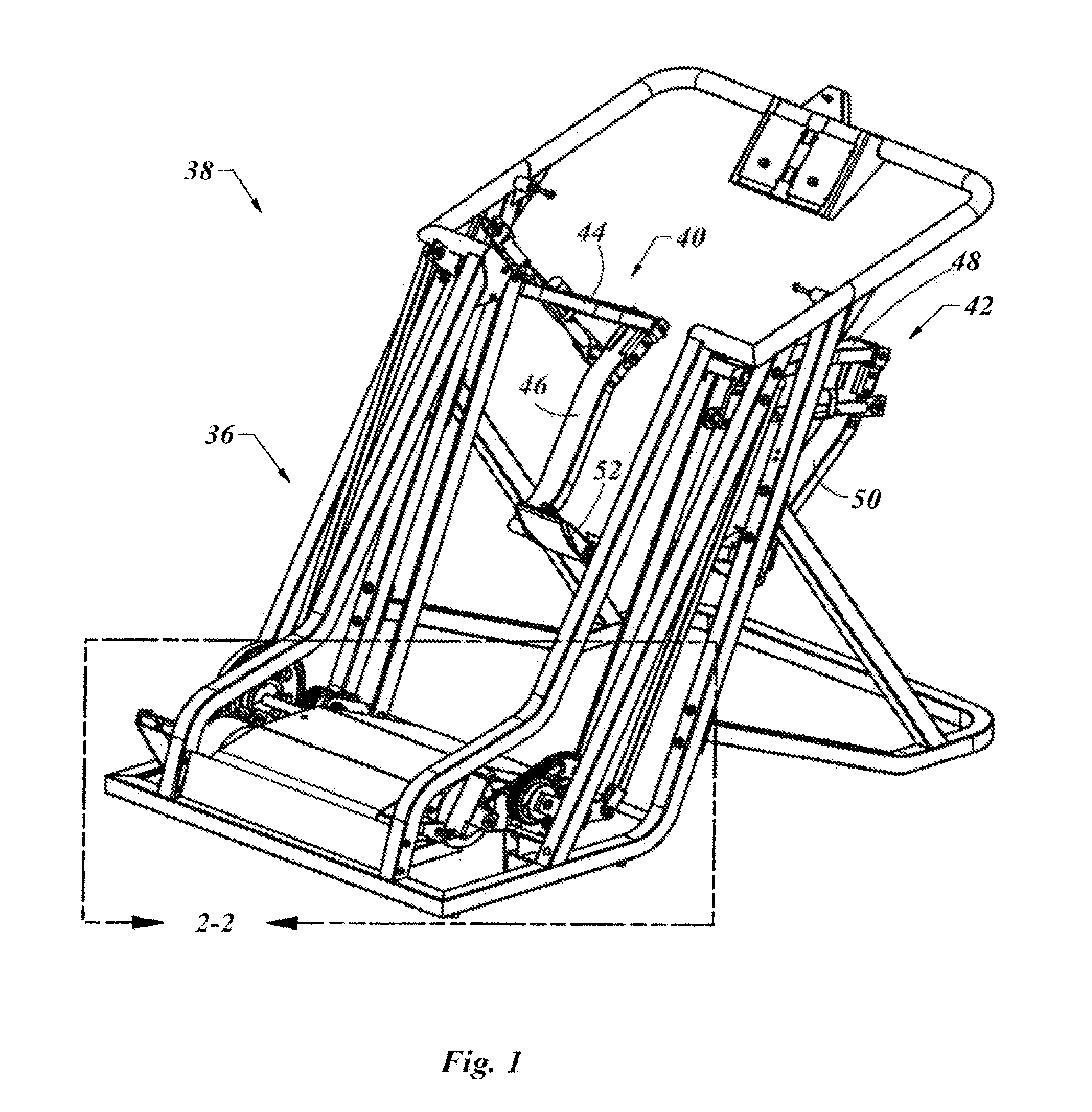
[0048]With reference to the illustrative drawings, and particularly to FIGS. 1-6, there is shown an exercise device in the form of a multifunctional adaptive training device 38. This embodiment of the invention may include a frame 36 supporting a pair of leg linkages including a first leg linkage 40 and a second leg linkage 42. The first leg linkage 40 may include a first upper link 44 coupled to a first lower link 46. In a like manner, a second leg linkage 42 may include a second upper link 48 coupled to a second lower link 50. A foot support 52 may be positioned on a distal end of each of the first lower link 46 and the second lower link 50. A user may position themselves with one foot on each of the foot supports 52 and perform a variety of different exercises.

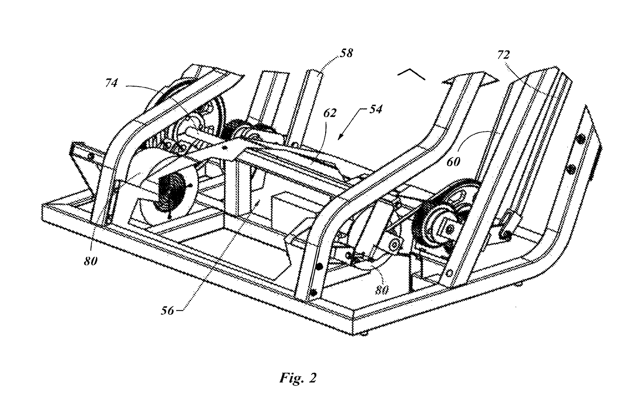
[0049]The foot supports 52 are linked from one to the other by way of a first transfer system 54 and a second transfer system 56. The first transfer system 54 may include a first transfer member 58, coupled to the first upp...


PUM


Abstract

An exercise device for performing a variety of movement patterns is provided, having an upper link pivotally mounted to a lower leg link and a foot support on a distal end of the lower leg link. A first transfer system is movably coupled to a frame and including a first transfer member coupled to the first upper leg link and a second transfer member coupled to the second upper leg link, thereby enabling substantially reciprocating motion of the first leg link relative to the second leg link. A second transfer system is also provided and may be movably coupled to the frame and including a pair of third transfer members coupled to each of a pair of fourth transfer members by way of each of a pair of transfer couplings, each movably mounted to the frame. The fourth transfer members may be coupled to the first lower leg link and the second lower leg link, whereby movement of the first lower leg link causes movement of the second lower leg link irrespective of movement of the upper leg links thereby providing a stable platform for the user and also enabling an infinite number of gait patters by the user.

Description

CROSS-REFERENCE TO RELATED APPLICATIONS[0001]This Patent Application is a Continuation-in-Part of Ser No. 12 / 591,672, filed 27 Nov. 2009, now U.S. Pat. No. 7,833,134, which is a Divisional Application of Ser. No. 11 / 501,780, filed 10 Aug. 2006, now U.S. Pat. No. 7,645,215. This Patent Application is based on Provisional Application Ser. No. 61 / 331,520 filed on 5 May 2010.FIELD OF THE INVENTION[0002]The present invention generally relates to exercise equipment and more particularly, to exercise equipment which simulate or facilitate ambulatory human movement.BACKGROUND OF THE INVENTION[0003]Exercise is a necessary part of a healthy lifestyle. Without proper exercise, muscle tissue decreases, the mineral density of bones decline and people tend toward storing more fat weight. This contributes to a variety of health issues including cardiovascular disease, osteoporosis and diabetes. A common aerobic exercise is running. The ground pounding action of running can cause joint issues in so...

Claims


Application Information

Patent Timeline
Patent Type & Authority Patents(United States)
IPC IPC(8): A63B22/00A63B22/04A63B71/00
CPCA63B22/0017A63B22/0292A61H1/0237A61H1/0262A63B21/00178A63B21/155A63B22/001A63B22/0056A63B22/02A63B22/0664B62M1/24B62M1/30A63B21/225A63B22/0046A63B22/203A63B22/208A63B22/20A63B21/0083A63B69/0064A63B2022/0051A63B2220/56A63B2230/015A63B2022/0688A63B2022/0682A63B2022/0038A63B22/04
Inventor GORDON, JOEL D.ABELBECK, KEVIN G.ROSS, GLENN D.OLSCHANSKY, BRAD R.OLSCHANSKY, SCOTT M.
Owner EXERCITING
Why Eureka
Try Eureka