Lighting device, display, and method for manufacturing the same

a technology of light source and light source, which is applied in the direction of optical elements, organic semiconductor devices, instruments, etc., can solve the problems of large-scale light source manufacturing difficulties, inability to create uniform surface light, and high cost of typical led packaging, so as to achieve the effect of significantly reducing the thickness of the overall packaging structur

Inactive Publication Date: 2012-02-07
LUXINGTEK
View PDF9 Cites 43 Cited by
  • Summary
  • Abstract
  • Description
  • Claims
  • Application Information

AI Technical Summary

Benefits of technology

[0013]Yet another objective of this invention is to provide a novel lighting device and a method for manufacturing the lighting device, where the reflector for forming inner reflections is adopted allowing LED light to travel within the internal structure without using a conventional diffuser. Thus, the thickness of the overall packaging structure can be significantly reduced.
[0014]Further objective of this invention is that LED dice are preferably adopted to the light source units. Since LED dice are much cheaper than packaged LEDs, the present invention integrates the conventional coating processes and the PCB assembly processes into each other. LED dice rather than the packaged LED are adopted in the present invention.

Problems solved by technology

However, it is well known in the field that these typical LED packaging are costly (as compared to a LED bare die) and cannot be used to create an uniform surface light without a sophisticated optical design and costly manufacturing processes.
However, it is know in the field that a large-scale light guide plate faces manufacturing difficulty and is costly to be utilized in a large-scale display.
Moreover, because light emitted from each LED spreads out through the entire light guide plate, no regional on / off control can be established.
Therefore the edge-type backlight module cannot be used for LCD requiring local dimming features.
In spite of the direct-type backlight module being suitable for the large-scale displays, it can be well imagined that the direct-type backlight module is not only too complicated to arrange the light sources onto the bezel but also too thick since the diffuser for scattering light has to be spaced apart from the LEDs.

Method used


Image

  • Lighting device, display, and method for manufacturing the same
  • Lighting device, display, and method for manufacturing the same
  • Lighting device, display, and method for manufacturing the same

Examples


first embodiment

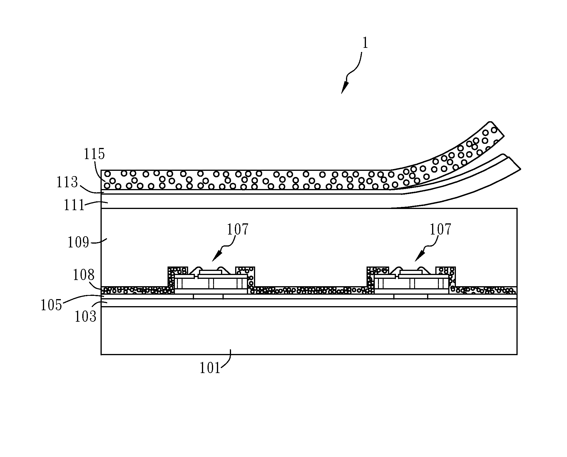
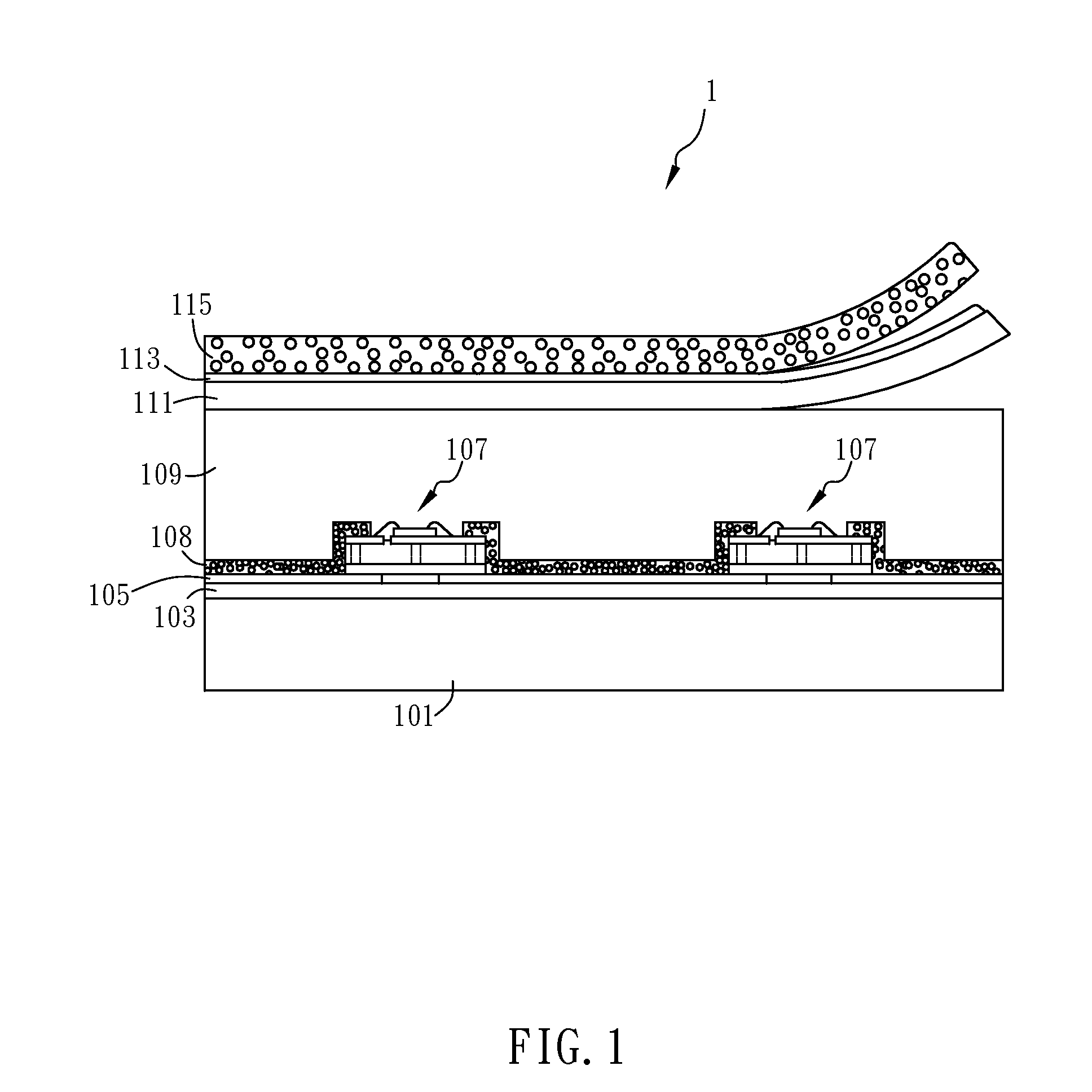
[0033]The present invention relates to a lighting device, for example, a direct-type backlight module. FIG. 1 shows the lighting device 1 in accordance with the present invention. The lighting device 1 at least comprises a substrate 101, an electrode layer 105 patterned on the substrate 101, and a plurality of light source units 107. The light source units 107 are arranged onto the substrate to electrically connect with the electrode layer 105. In this embodiment, it is characterized in that each light source unit 107 includes a circuit board unit and at least one light emitting diode (LED) die being packaged onto the circuit board unit. Certainly, the lighting device 1 further comprises a control circuit (not shown in the figures) electrically connects with the electrode layer 105. The control circuit is capable of selectively activating the plurality of light source units 107 through the electrode layer 105 according to the displayed image to achieve the objective of local dimming...

fourth embodiment

[0050]It is noted that the number of LED dice packaged onto the light source unit 107 is not limited. FIG. 13A to FIG. 13C illustrate the present invention. In this embodiment, a plurality of LED dice 107e are bonded onto one circuit board unit 107b to form one light source unit 107. The metal layers 107c are purposely designed for electrically connecting with the patterned electrode layer 105, as shown in FIG. 13B. The patterned electrode layer 105 is also designed to create X-Y passive matrix driving. Thus, the LED dice 107e can be independently controlled via the electrode layer 105. Certainly, a plurality of light source units 107 can be further assembled onto the substrate 101 and connected with the electrode layer 105, as shown in FIG. 13C. Alternatively, as shown in FIGS. 13D to 13F, the electrical connection between the light source units 107 and the electrode layer 105 can also be formed by creating holes or recesses on the substrate 101, where the size and shape of the hol...

fifth embodiment

[0051]The fifth embodiment discloses a lighting device 1 formed with partitions between the light source units 107. As shown in FIG. 14A and FIG. 14B, a plurality of isolation grid structures 121 is formed within the transparent layer 109 to partition the plurality of light source units 107. The isolation grid structures 121 can be formed by screen printing, inkjet printing, stamping, or any other direct pattern-printing processes in advance and the transparent layer 109 be coated subsequently. Alternatively, the transparent layer 109 can be formed in advance and the isolation grid structures 121 being planted into the transparent layer 109 which can be made by any conventional molding process or knife punching method. It is noted that the materials of isolation grid structures 121 is not limited and is preferred to be white and non-transparent or semi-transparent, so as to block the light from the adjacent the light source units 107. The lighting device 1 of this embodiment is to p...


PUM


Abstract

A display, a lighting device and a method for manufacturing the lighting device are provided. The lighting device comprises a substrate, an electrode layer, a plurality of light source units and a light scattering layer, which is covered by a transparent layer and a reflector layer to create a uniform surface light within an ultra thin format. A yellow phosphor layer is disposed above the reflector layer to create white light when a blue LED or UV LED is used. The lighting device also provides a unique electrode layout design which can be applied for local dimming control and can be easily applied for large size product applications.

Description

CROSS-REFERENCES TO RELATED APPLICATIONS[0001]Not applicable.BACKGROUND OF THE INVENTION[0002]1. Field of the Invention[0003]The present invention relates to a novel lighting device being able to produce a uniform surface light with an ultra thin format and a method for manufacturing the lighting device.[0004]2. Descriptions of the Related Art[0005]Typical LED packaging comprises attaching an LED die onto a lead frame made of injected aluminum piece, wire bonding to electrically connect LED to the lead frame, and encapsulating the LED, wire bonds and lead frame with an optical clear epoxy using a molding process, where two leads come out of the molded encapsulant for electrical connection. This type of LED packaging structure produces a “dot” light source and is widely adapted for general lighting, message board and light box. Another type of LED packaging, where the LED is packaged into a very compact format used for SMT assembly, is widely used for LCD backlight unit applications....

Claims


Application Information

Patent Timeline
Patent Type & Authority Patents(United States)
IPC IPC(8): H01L33/00H01L21/00
CPCG02F1/133606G02F1/133611G02B5/0236G02B5/0278G02F1/133603H01L2924/12041H01L2224/16225H01L24/16H01L2224/48227H01L2224/48091H01L33/507H01L2251/5369H01L25/0753H01L33/505H01L2933/0091G02B2207/113G02B2207/115H01L24/48H01L2224/4911H01L2924/19107G02F1/13338G02F1/133605G02F1/13362H01L51/5268H01L27/322G02F2001/13324G02F2001/133342G02F2001/133601G02F2001/133607G02F2001/133612G02F2001/133614G02F2001/133628H01L2924/00014H01L2924/00H01L2924/12044H01L2924/181H01L2924/14H01L2224/48237H01L24/49G02F1/13324G02F1/133342G02F1/133601G02F1/133612G02F1/133614G02F1/133628G02F1/133607H10K59/38H10K50/854H10K2102/331H01L2924/00012H01L2224/45099H01L2224/45015H01L2924/207
Inventor ING, WEN-CHIUNHOU, WEI-HSIN
Owner LUXINGTEK
Why Eureka
Try Eureka