Illumination device and liquid crystal display device

a technology of liquid crystal display and illumination device, which is applied in the direction of cathode-ray/electron-beam tube circuit elements, lighting and heating apparatus, instruments, etc., can solve the problems of inability to maintain stable color temperature and stable luminance, and affecting the accuracy of detection. , to achieve the effect of accurate detection temperature, accurate temperature detection, and small temperature chang

Active Publication Date: 2012-02-07
SHARP KK
View PDF27 Cites 26 Cited by
  • Summary
  • Abstract
  • Description
  • Claims
  • Application Information

AI Technical Summary

Benefits of technology

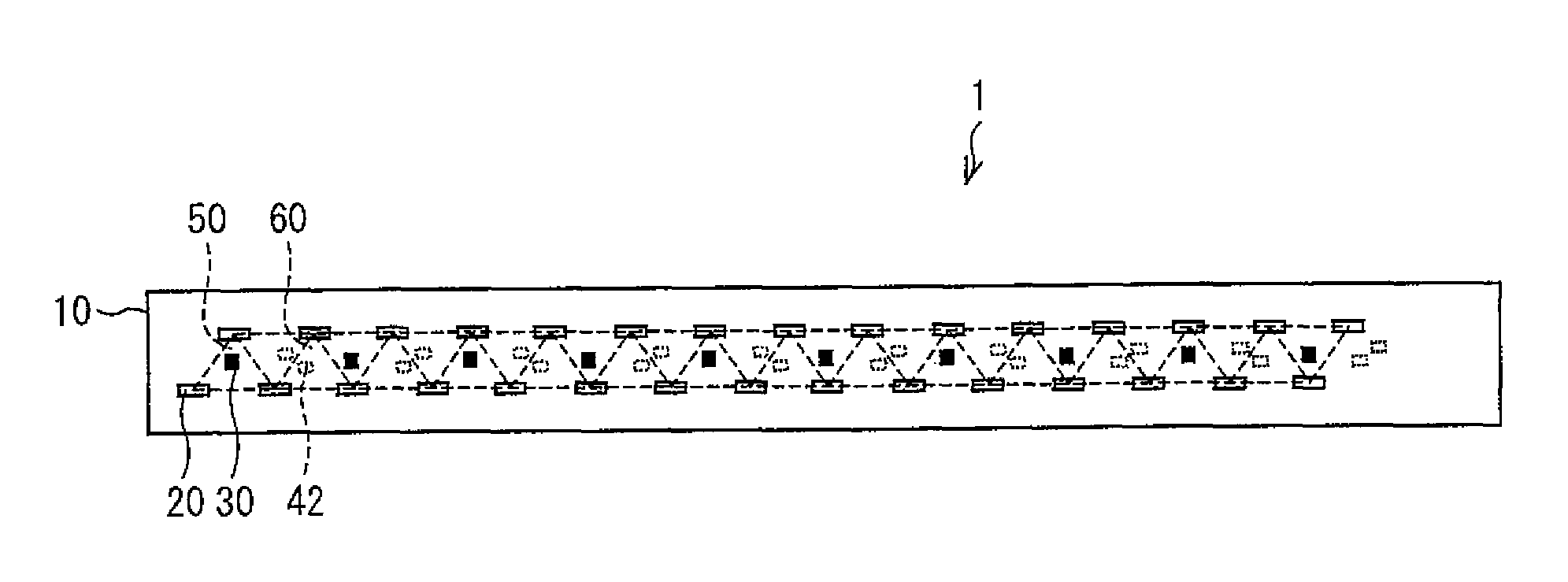
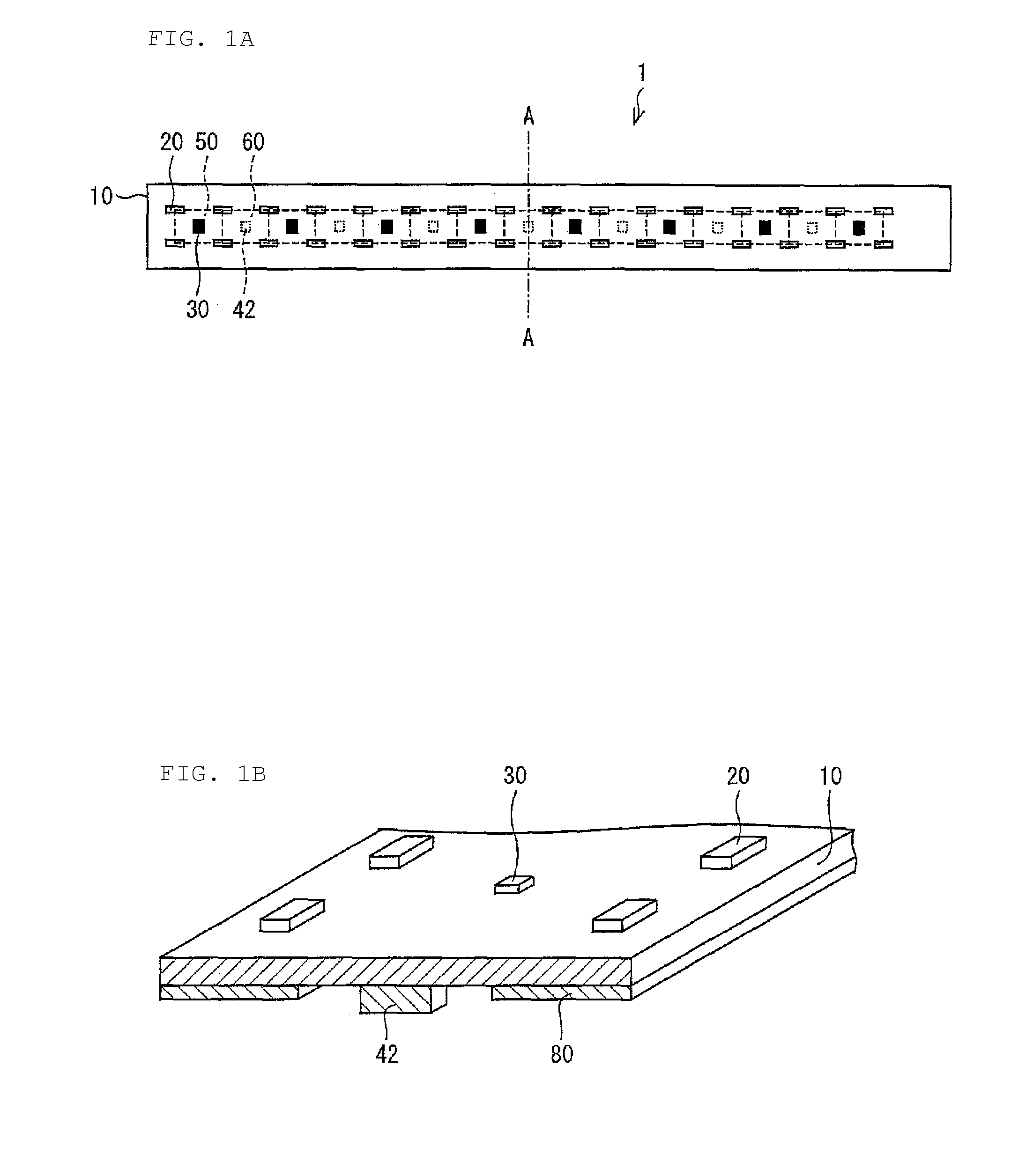
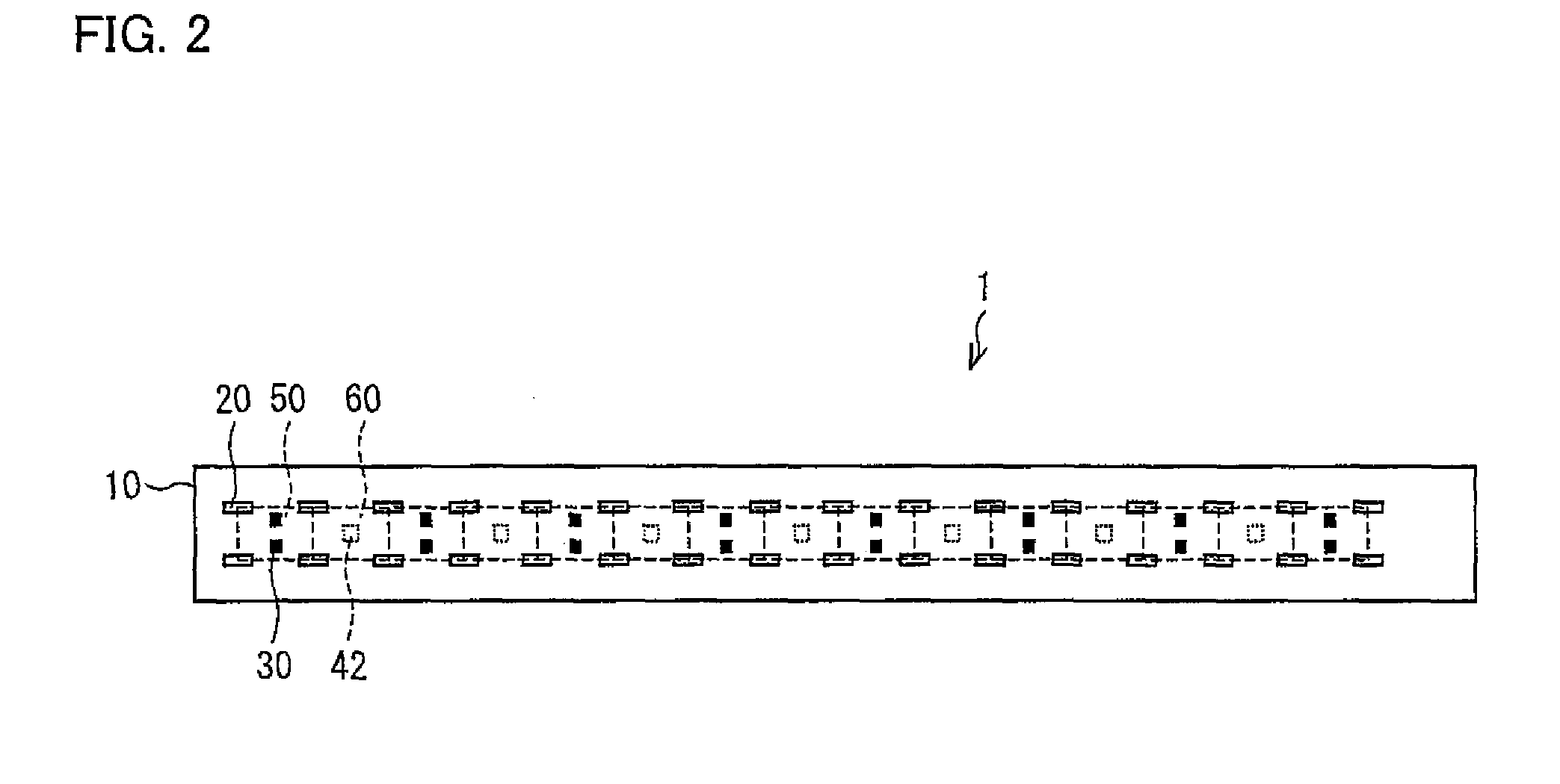
[0016]When in operation, the driving section generates heat and causes an increase in temperature of a specific area of the substrate. In the area of the substrate in which there is an increase in temperature due to the heat generated by the driving section, it is difficult to accurately detect the temperature of heat transferred from the luminous bodies. In this configuration, the driving section is disposed outside of a polygonal area determined by vertices corresponding to luminous bodies surrounding the temperature detecting section. Preferably, the driving section and the temperature detecting section are disposed in different polygonal areas (i.e., in different “polygonal areas” among the plurality of “polygonal areas”). In other words, the temperature detecting section is disposed on the substrate so as to be in an area that is relatively small in temperature change that is caused by the heat generated by the driving section during operation. Then, the temperature detecting section detects the temperature in the polygonal area in which the temperature detecting section is disposed. For this reason, the temperature detecting section can accurately detect the temperature in the polygonal area in which the temperature detecting section is disposed, without being affected by the heat generated by the driving section.
[0017]The temperature in the polygonal area in which the temperature detecting section is disposed is correlated with the temperatures of the luminous bodies. Accordingly, this configuration makes it possible to estimate the temperatures of the luminous bodies in accordance with temperature data detected by the temperature detecting section. Hence, it is possible to efficiently make temperature corrections and to exhibit a stable color temperature and luminance.
[0019]The illumination device can efficiently make temperature corrections, thus exhibiting a stable color temperature and luminance. Accordingly, the above configuration makes it possible to achieve a liquid crystal display device to be stable in color temperature and luminance.

Problems solved by technology

In general, LEDs have characteristics such that their relative luminance tends to decrease with an increase in ambient temperature, i.e., have such a problem that their light efficiency changes depending on fluctuations in ambient temperature.
Accordingly, the following problem arises: namely, based on the preset temperature, a stable color temperature and a stable luminance cannot be maintained by merely controlling driving in accordance with a preset temperature.
However, a technique for appropriately detecting the temperature of each individual LED of each area in an area-active backlight and controlling the driving of the area active backlight in accordance with that temperature remains undeveloped.

Method used


Image

  • Illumination device and liquid crystal display device
  • Illumination device and liquid crystal display device
  • Illumination device and liquid crystal display device

Examples


Embodiment Construction

[0035]Preferred embodiments of the present invention are described below with reference to FIG. 1A through FIG. 11. The present invention, however, is not limited to the preferred embodiments described below.

[0036]As illustrated in FIG. 5, a liquid crystal display device 3 in accordance with the present preferred embodiment includes a liquid crystal panel 70, a liquid crystal panel driving circuit 71, a controller 72, an illumination device 2, an optical member (not shown) such as a diffusion plate, and a power supply control section 73. The controller 72 controls the liquid crystal panel driving circuit 71 and the illumination device 2 in accordance with input video data. In response to the control from the controller 72, the liquid crystal display panel driving circuit 71 drives the liquid crystal panel 70, and the illumination device 2 radiates light. The light radiated from the illumination device 2 is supplied to the liquid crystal panel 70 through a diffusion plate (not shown)...


PUM

PropertyMeasurementUnit
voltage Vfaaaaaaaaaa
electric poweraaaaaaaaaa
voltages Vfaaaaaaaaaa

Abstract

An illumination device includes an LED package, an LED driver including an FET, and a thermistor disposed on a substrate. A plurality of such LED packages are disposed on the substrate such that a first area and a second area, each determined by vertices corresponding to LED packages, are defined on the substrate. The thermistor is disposed in the first area, and the FET is disposed in the second area, which is outside of the first area. The thermistor detects a temperature in the first area. Such a configuration allows the thermistor to detect, in accordance with the temperature in the area, the temperature of heat transferred from the LED packages, without being affected by heat generated by the FET. This makes it possible to efficiently make temperature corrections to stabilize color temperature and luminance.

Description

BACKGROUND OF THE INVENTION[0001]1. Field of the Invention[0002]The present invention relates to illumination devices and liquid crystal display devices, especially to an illumination device and a liquid crystal display device, each of which is stable in color temperature and luminance.[0003]2. Description of the Related Art[0004]Cold cathode fluorescent lamps (hereinafter referred to as “CCFLs”) have been conventionally used as backlights incorporated in back of liquid crystal panels of transmissive liquid crystal display devices used in laptop personal computers, computer monitors and television receivers. However, in recent years, due to the amelioration, among others, of the light efficiency of light-emitting diodes (hereinafter referred to as “LEDs”) and to the reduction of their cost, LEDs are increasingly being used as backlights of liquid crystal display devices.[0005]LED backlight devices can either be of the direct type, where LEDs are arrayed below the back surface of a d...

Claims


Application Information

Patent Timeline
Patent Type & Authority Patents(United States)
IPC IPC(8): G02F1/1333H05B44/00
CPCG09G3/3426H05B33/0872H05B33/0821G02F1/133603G09G2320/041H05B45/28H05B45/48H05B45/40
Inventor SUMINOE, SHINJIYAMAMOTO, TOMOHIKOTOMIYOSHI, AKIRAINOUE, NAOTO
Owner SHARP KK
Why Eureka
Try Eureka