Eureka AIR delivers breakthrough ideas for toughest innovation challenges, trusted by R&D personnel around the world.

Electrically resistive coating for remediation (regeneration) of a diesel particulate filter and method

Inactive Publication Date: 2012-02-14
HRL LAB
View PDF7 Cites 6 Cited by
  • Summary
  • Abstract
  • Description
  • Claims
  • Application Information

AI Technical Summary

Benefits of technology

[0008]Embodiments of the present invention provide a resistively heated diesel particulate filter that can substantially maintain its resistance during an operating range of a diesel particulate filter. Embodiments of the present invention also provide a method of resistively heating a diesel particulate filter.
[0011]According to another embodiment of the present invention, a resistively heated diesel particulate filter is provided. The resistively heated diesel particulate filter includes a diesel particulate filter having an inlet surface; and at least one resistive coating on the inlet surface. The at least one resistive coating has a first terminal and a second terminal for applying electrical power to resistively heat the at least one resistive coating to increase the temperature of the diesel particulate filter to a regeneration temperature. The at least one resistive coating includes a metal constituent and a semiconductor constituent. The metal constituent and the semiconductor constituent are selected to substantially maintain a resistance of the at least one resistive coating in the range of minus 50% to plus 25% in the operating temperature range of the diesel particulate filter.

Problems solved by technology

The downside of either approach is that not all the heat transferred to the exhaust gas is transferred to the DPF.
Much of the exhaust passes through the DPF with incomplete heat transfer, creating a large inefficiency.
The problem is worse for the case of the fuel burner.
Here the inefficiency is compounded by the creation of additional particulates and hydrocarbon emissions, a lower exhaust oxygen concentration, and shorter lifetimes for the DPF due to cracking from thermal gradients.
In both cases, parasitic absorption of microwave energy by the soot / particulate effectively reduces the regeneration efficiency to a undesirable level.
However, the heating element of the filter system may suffer from changing resistivity due to changing temperature throughout a regeneration cycle.

Method used


Image

  • Electrically resistive coating for remediation (regeneration) of a diesel particulate filter and method
  • Electrically resistive coating for remediation (regeneration) of a diesel particulate filter and method
  • Electrically resistive coating for remediation (regeneration) of a diesel particulate filter and method

Examples


Embodiment Construction

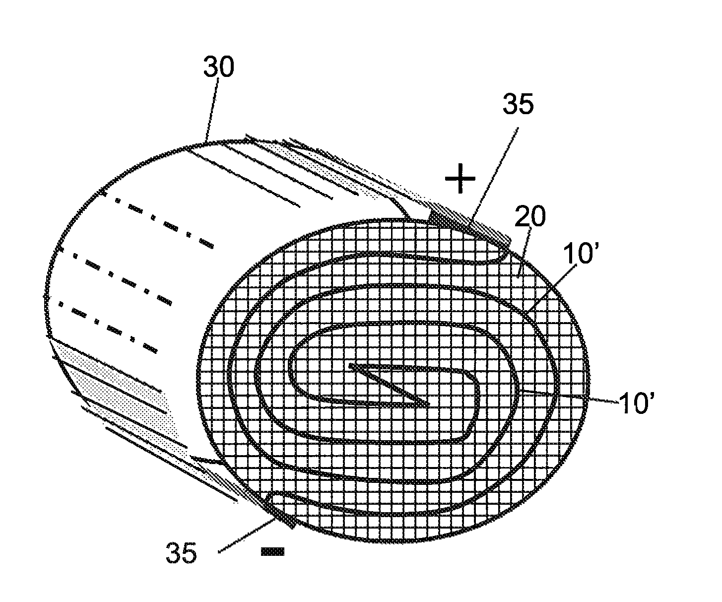
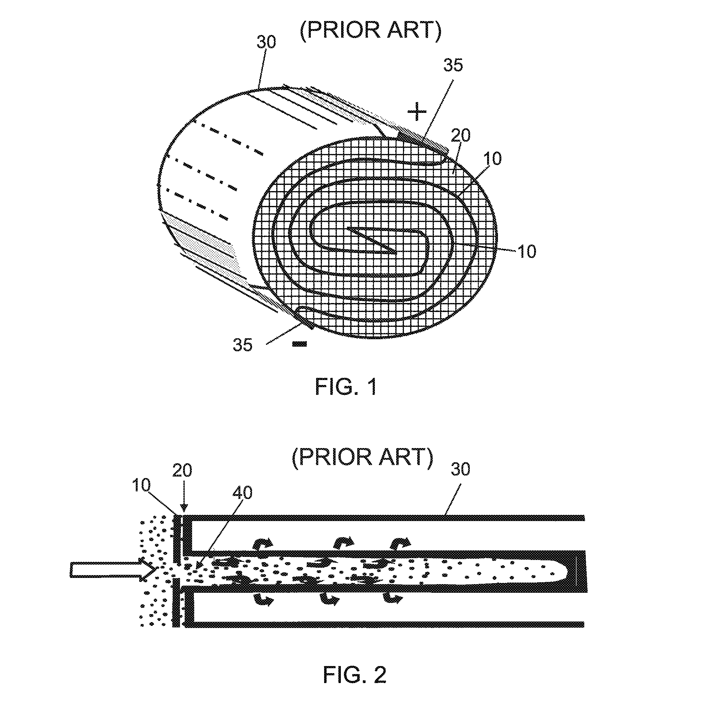
[0019]Embodiments of the present invention provide a DPF that includes one or more adaptive resistive coatings as an integrated heating element to increase the temperature of the DPF to initiate filter regeneration (a.k.a. remediation). The adaptive resistive coatings are designed to have a relatively small resistance variation throughout the regeneration cycle. Embodiments of the present invention also provide a method of regenerating a DPF by using an integrated adaptive resistive coating as a heating element.

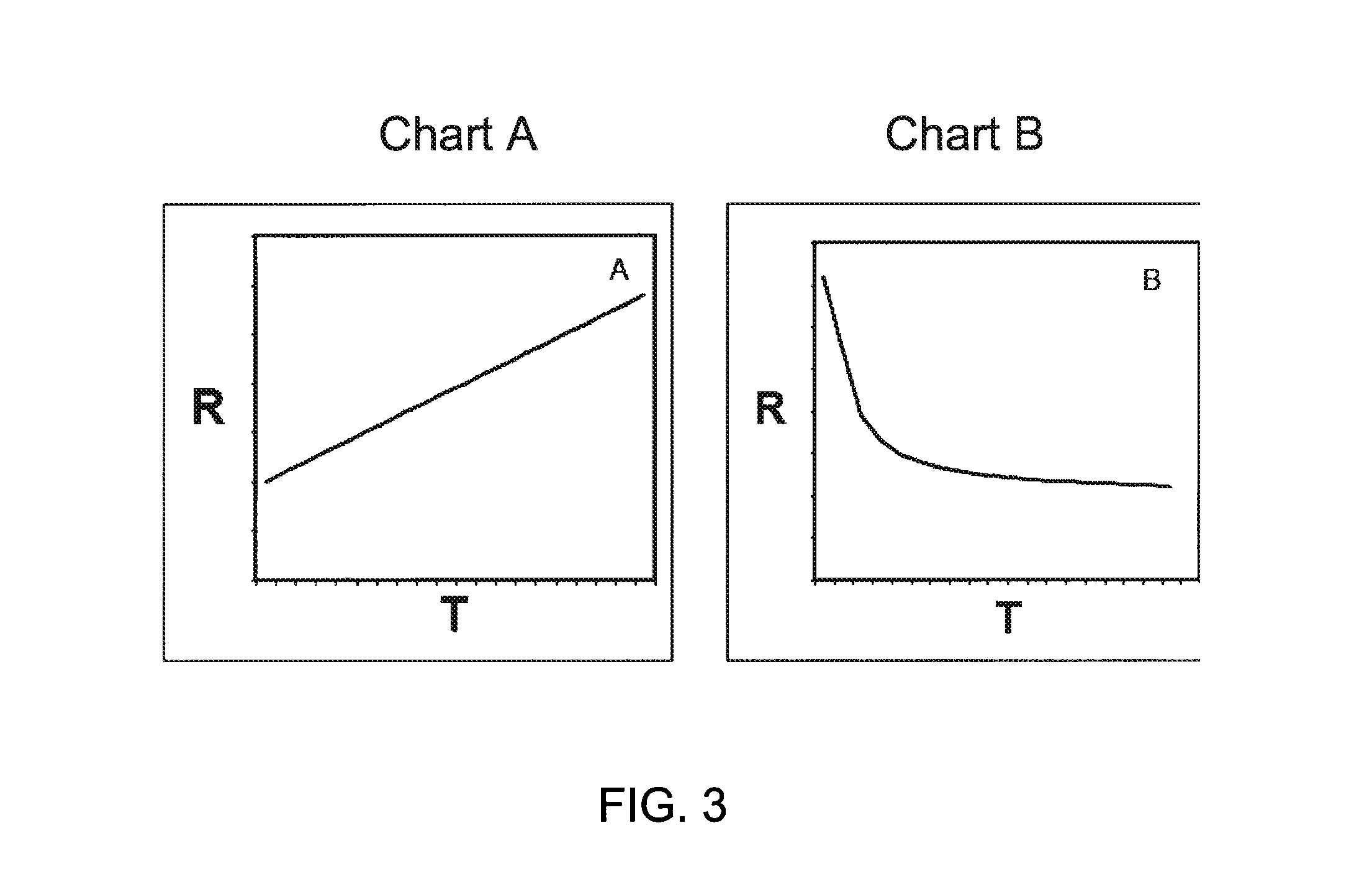
[0020]Initial results of using a purely metallic thick film coating as a resistive heater illustrate some fundamental problems including robustness, thermal runaway when the resistance is too low, and insufficient power when the resistance is too high. Embodiments of the present invention provide a thick film coating material where its resistance adapts as the temperature changes. An exemplary resistive coating with such property may be created by using a combination of mater...


PUM

PropertyMeasurementUnit
Fractionaaaaaaaaaa
Fractionaaaaaaaaaa
Temperatureaaaaaaaaaa

Abstract

A resistively heated diesel particulate filter (DPF). The resistively heated DPF includes a DPF having an inlet surface and at least one resistive coating on the inlet surface. The at least one resistive coating is configured to substantially maintain its resistance in an operating range of the DPF. The at least one resistive coating has a first terminal and a second terminal for applying electrical power to resistively heat up the at least one resistive coating in order to increase the temperature of the DPF to a regeneration temperature. The at least one resistive coating includes metal and semiconductor constituents.

Description

STATEMENT REGARDING FEDERALLY SPONSORED RESEARCH OR DEVELOPMENT[0001]This invention was made with U.S. Government support under Contract No. DE-FC-04-03AL67635 awarded by the Department of Energy. The U.S. Government has certain rights to this invention.BACKGROUND[0002]A diesel particulate filter (DPF) is a device designed to remove diesel particulate matter or soot from the exhaust gas of a diesel engine. A well known DPF type is a wall-flow type filter made of cordierite (a ceramic material). The DPF is designed to force the exhaust gas from a diesel engine to flow through the wall of the filter while the particulates collect on the filter wall. Wall-flow DPF usually remove 85% or more of the soot, and can at times achieve efficiencies of close to 100%. A diesel engine equipped with functioning DPF emits no visible smoke from its exhaust pipe.[0003]However, after a period of operation, the DPF must be regenerated (i.e., removal of collected particulates or soot from the wall of th...

Claims


Application Information

Patent Timeline
IPC IPC(8): F01N3/10B01D50/00
CPCB01D46/0063F01N3/027F01N2240/16F01N2330/30F01N2330/60B01D46/84
Inventor PHELPS, AMANDA C.KIRBY, KEVIN K.GREGOIRE, DANIEL J.
Owner HRL LAB
Why Eureka
Eureka Blog
Learn More