

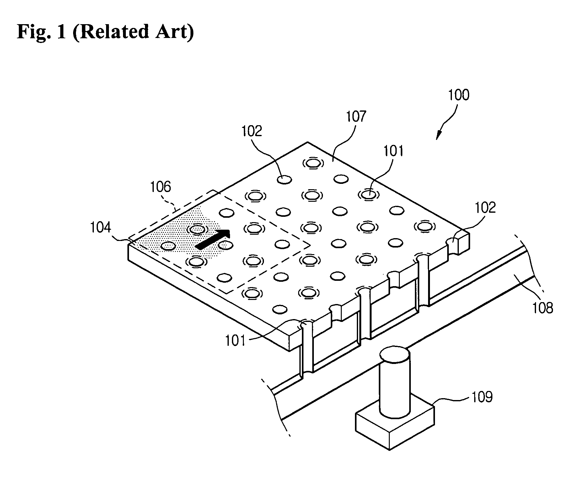
Support platform of non-contact transfer apparatus
a technology of support platform and transfer apparatus, which is applied in the direction of conveyors, lighting and heating apparatus, furniture, etc., can solve the problems of increasing process costs, object scratching, uneven pressure distribution on the active surface of the support platform, etc., and achieves the effect of stably transferring an object and reducing the consumption of air
- Summary
- Abstract
- Description
- Claims
- Application Information
AI Technical Summary
Benefits of technology
Problems solved by technology
Method used
Image

Examples
first embodiment
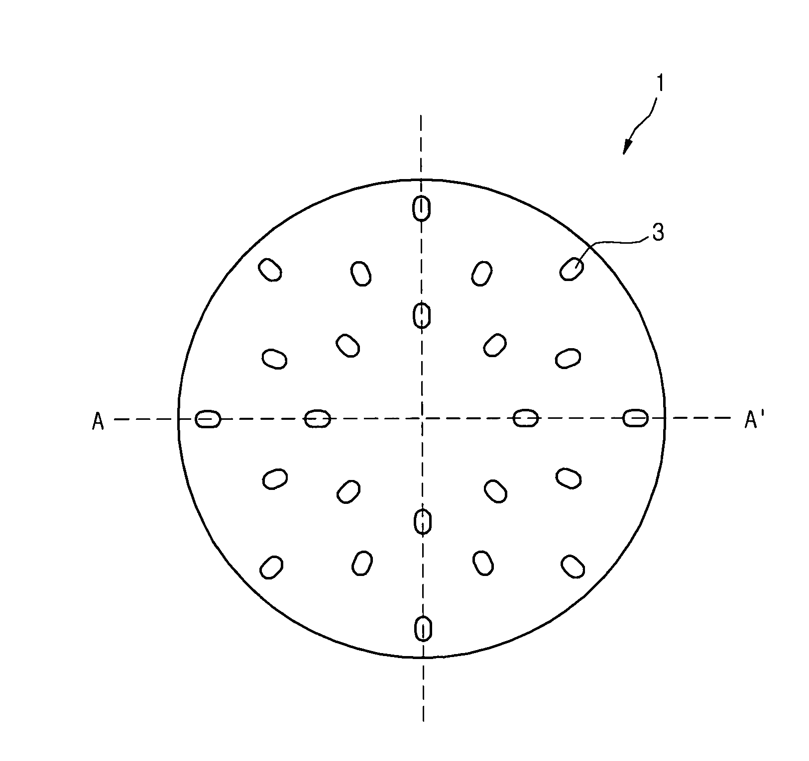
[0039]FIG. 3 is a schematic top view of a support platform of a non-contact transfer apparatus according to the present invention.
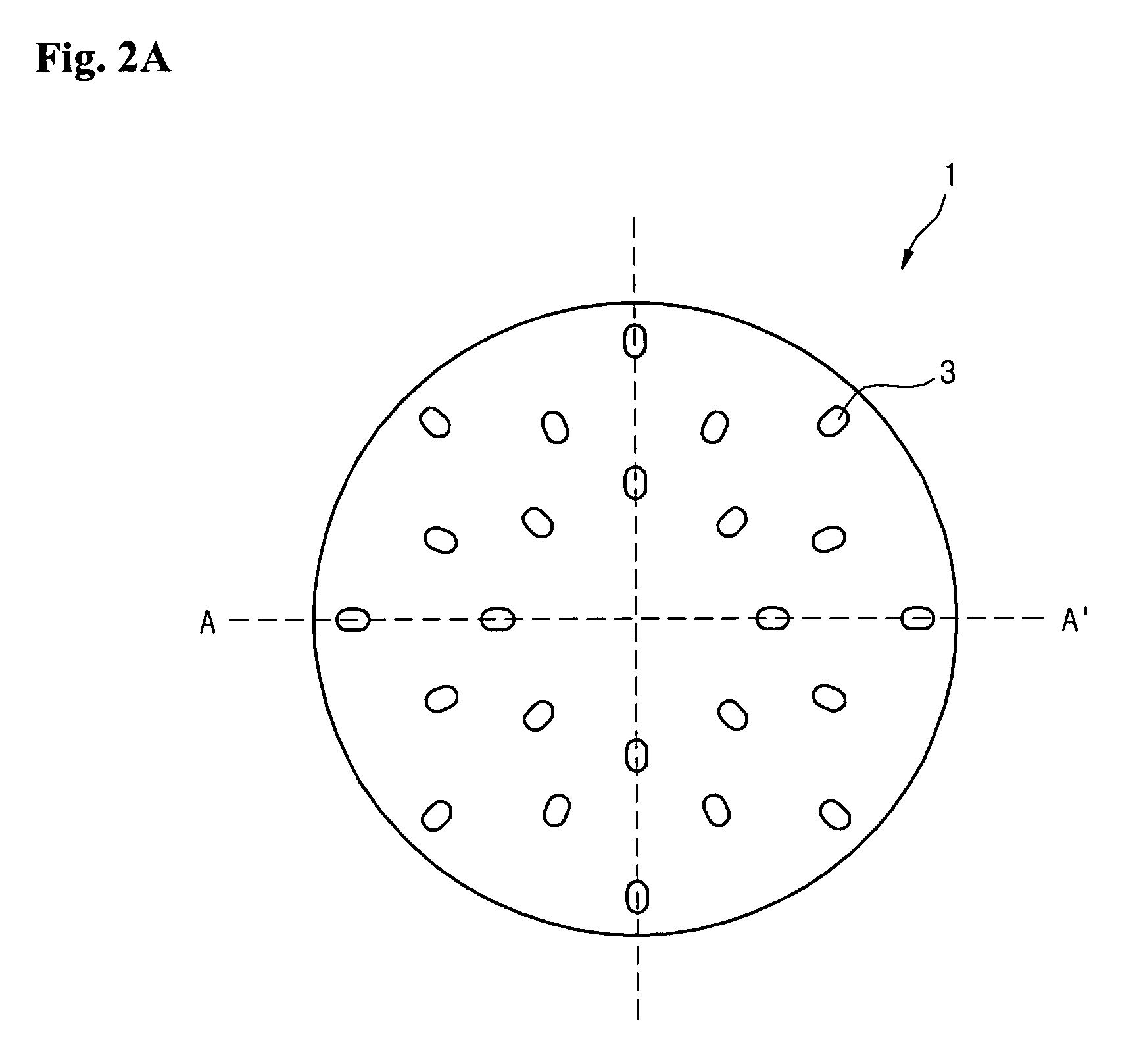
[0040]As shown in FIG. 3, a support platform of this embodiment includes a guide pad 10 on which a plurality of air intake hole portions 1 are formed along a plurality of lines. A plurality of sub-holes (3 of FIG. 2A) are radially formed through each air intake hole portion 1. A plurality of air exhaust holes 5 are formed along lines between the lines of the air intake hole portions 1. That is, the lines on which the air intake hole portions 1 are formed alternate with the lines on which the air exhaust holes 5 are formed. Air is introduced upwardly through the air intake hole portions 1 to transfer the object in a state where the object is lifted from the surface of the guide pad 10. Then, the air is exhausted downwardly through the air exhaust holes 5.
[0041]Unlike the guide pad 10 of FIG. 3, a guide pad on which the air intake hole portions 1 and the ai...
second embodiment
[0043]FIG. 4 is a schematic top view of a support platform of a non-contact transfer apparatus according to the present invention.
[0044]As shown in FIG. 4, a support platform of this embodiment includes a guide pad 12 on which a plurality of air intake hole portions 1 are formed along a plurality of lines. A plurality of sub-holes (3 of FIG. 2A) are radially formed through each air intake hole portion 1. A plurality of substantially rectangular slots 14 are formed along lines between the lines of the air intake hole portions 1. That is, the lines on which the substantially rectangular slots are formed alternate with the rectangular slots 14.
[0045]By using the substantially rectangular slots 14, the air introduced through the air intake hole portions 1 can be more effectively exhausted, thereby preventing air pressure formed by the introduced air from excessively increasing and providing a stable air cushion.
[0046]According to this embodiment, since the air is uniformly introduced th...
third embodiment
[0047]FIG. 5 is a schematic top view of a transfer apparatus having a support platform according to the present invention.
[0048]In FIG. 5, a support platform includes a guide pad 16 on which a plurality of air intake hole portions 1 are formed along a plurality of lines.
[0049]In this embodiment, the lines along which the air intake hole portions 1 are formed such that each group includes one or more lines. A plurality of substantially rectangular slots 18 are formed along lines between the groups each including one or more lines along which the intake hole portions are formed.
[0050]Alternatively, the lines along which the air intake hole portions 1 are formed may be grouped such that each group includes one or more lines and the lines along which the substantially rectangular slots are formed are also grouped such that each group includes one or more lines. The groups for the air intake hole portions 1 are arranged to alternate with the groups for the substantially rectangular slots...
PUM
 Abstract
Description
Claims
Application Information