USB connector

a technology of usb connectors and connectors, applied in the direction of coupling device connections, coupling protective earth/shielding arrangements, two-part coupling devices, etc., can solve the problems of lowering the signal transmission quality, data transmission speeds cannot meet the demand for quick transmission of a large amount of data within a limited time, and usb2.0 cannot be used with a high capacity hard disk drive or dvd copier, dvd player, etc., to achieve convenient fastening, avoid electromagnetic interferen

Inactive Publication Date: 2012-02-14
U D ELECTRONIC CORP
View PDF4 Cites 39 Cited by
  • Summary
  • Abstract
  • Description
  • Claims
  • Application Information

AI Technical Summary

Benefits of technology

[0009]The present invention has been accomplished under the circumstances in view. Therefore, it is the main object of the present invention to provide a USB connector, which has an electrically insulative rear cover fastened to the rear side of the first connection port and the top side of the connection member of bottom positioning member to shield the rear bonding portions of the first conducting terminals and second conducting terminals, the adapter terminals and the circuit module and to prohibit them from contacting the outer metal shield to cause a short circuit. Further, the rear cover has a plurality of locating flanges respectively from the front side and bottom sides thereof and respectively engaged into a receiving chamber and locating grooves of the connector body, assuring installation stability.
[0010]Further, the adapter board of the circuit module of the USB connector comprises two rows of first metal contacts and second metal contact for the bonding of the connection portions of the metal connection terminals and the connection portions of the adapter terminals respectively by means of surface mount technology so that the surface space of the adapter board can be fully utilized for the installation of electronic components to maintain their electric properties for best performance.
[0011]Further, the first connection port has the bottom side thereof mounted with a bottom positioning member. In an alternate form of the invention, the USB connector comprises a first connection port and a second connection port defined in the connector body thereof, a bottom positioning member located on the bottom side of the second connection port, a connection block located on the rear side of the bottom positioning member, and a metal shield surrounding the connector body for grounding. The first and second conducting terminals of the first and second connection ports and the metal connection terminals held in the connection block are well shield and isolated, avoiding electromagnetic interference. The electrically insulative component parts are conveniently fastened by hooking, assuring high connection stability for plugging and unplugging of an external USB connector.
[0012]Further, electronic components are installed in the adapter board. The adapter board comprises a set of first contacts and a set of second contact for the bonding of the rear bonding portion of the first conducting terminals and second conducting terminals of the first connection port and the rear bonding portion of the first conducting terminals and second conducting terminals of the second connection port respectively, and a set of first metal pads and a set of second metal pads respectively arranged at the rear side thereof corresponding to the electronic components. The electronic components include filter devices that can be CMC (common mode chokes), filter resistors and / or filter capacitors, and protection devices that can be TVS (transient voltage suppressor and / or varistor for protection against surge and / or static electricity. Thus, the electronic components of the adapter board effectively remove noises, electromagnetic interference, transient voltage, surge or static electricity during signal transmission, assuring signal transmission quality and reliability and avoiding signal interrogation or signal transmission failure.

Problems solved by technology

However, this design can simply be used in a peripheral apparatus (such as card reader, printer, memory stick, network phone, and network camera) of low driving power.
Nowadays, these data transmission speeds cannot satisfy the demand for quick transmission of a big amount of data within a limited time, i.e., USB2.0 cannot be used with a high capacity hard disk drive or DVD copier, DVD player or any advanced blue light electronic device.
However, due to limited internal space, it is difficult to install an extra row of conducting terminals in the connector body A. Further, when a big number of conducting terminals are installed in the connector body A, signal transmission interference may occur, lowering the signal transmission quality and increasing the risk of electromagnetic interference.
Further, after installation, the upper row of conducting terminals B and the bottom row of conducting terminals C may touch the metal shield D accidentally, causing a short circuit and increasing product defective rate.

Method used


Image

  • USB connector
  • USB connector
  • USB connector

Examples


Embodiment Construction

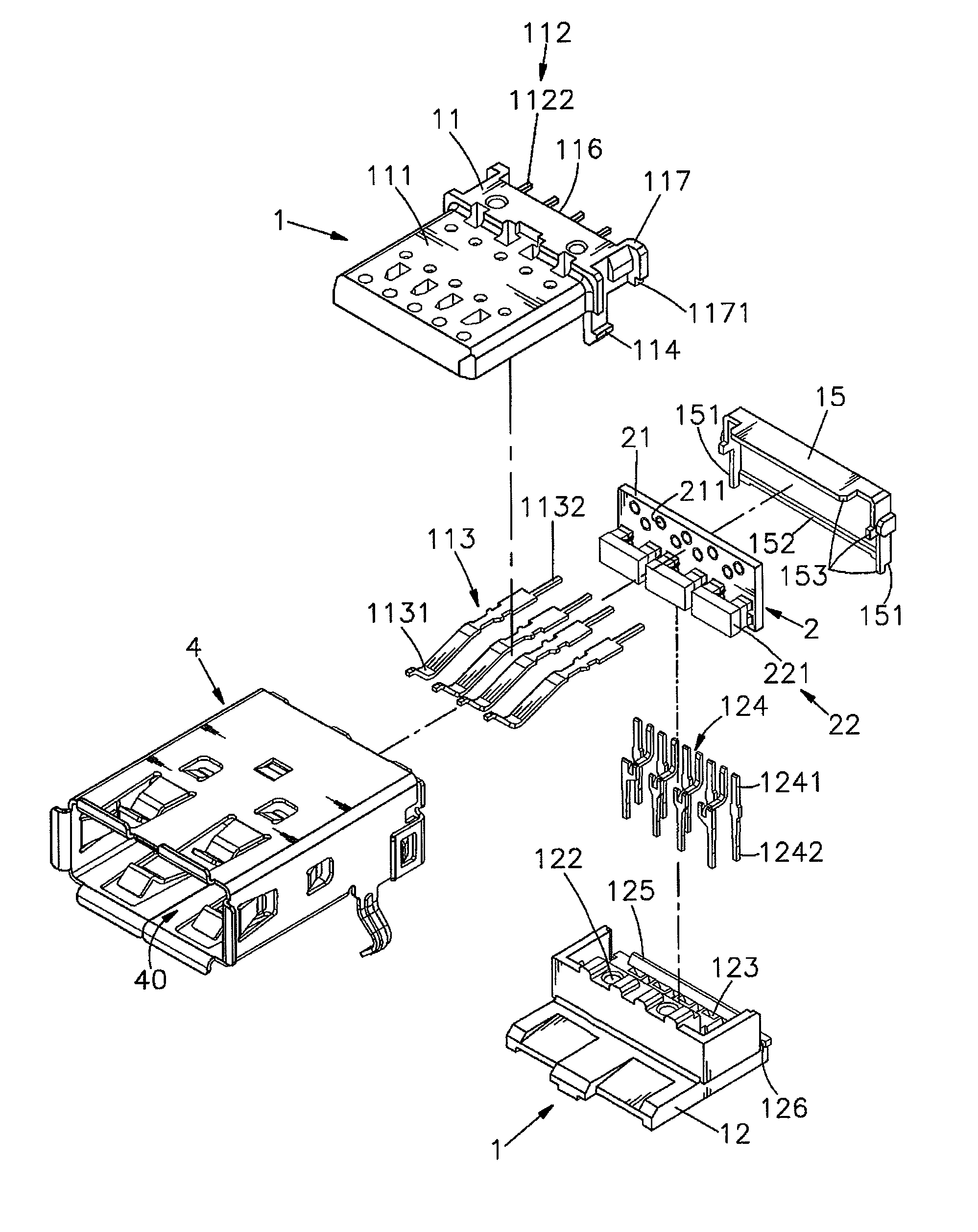
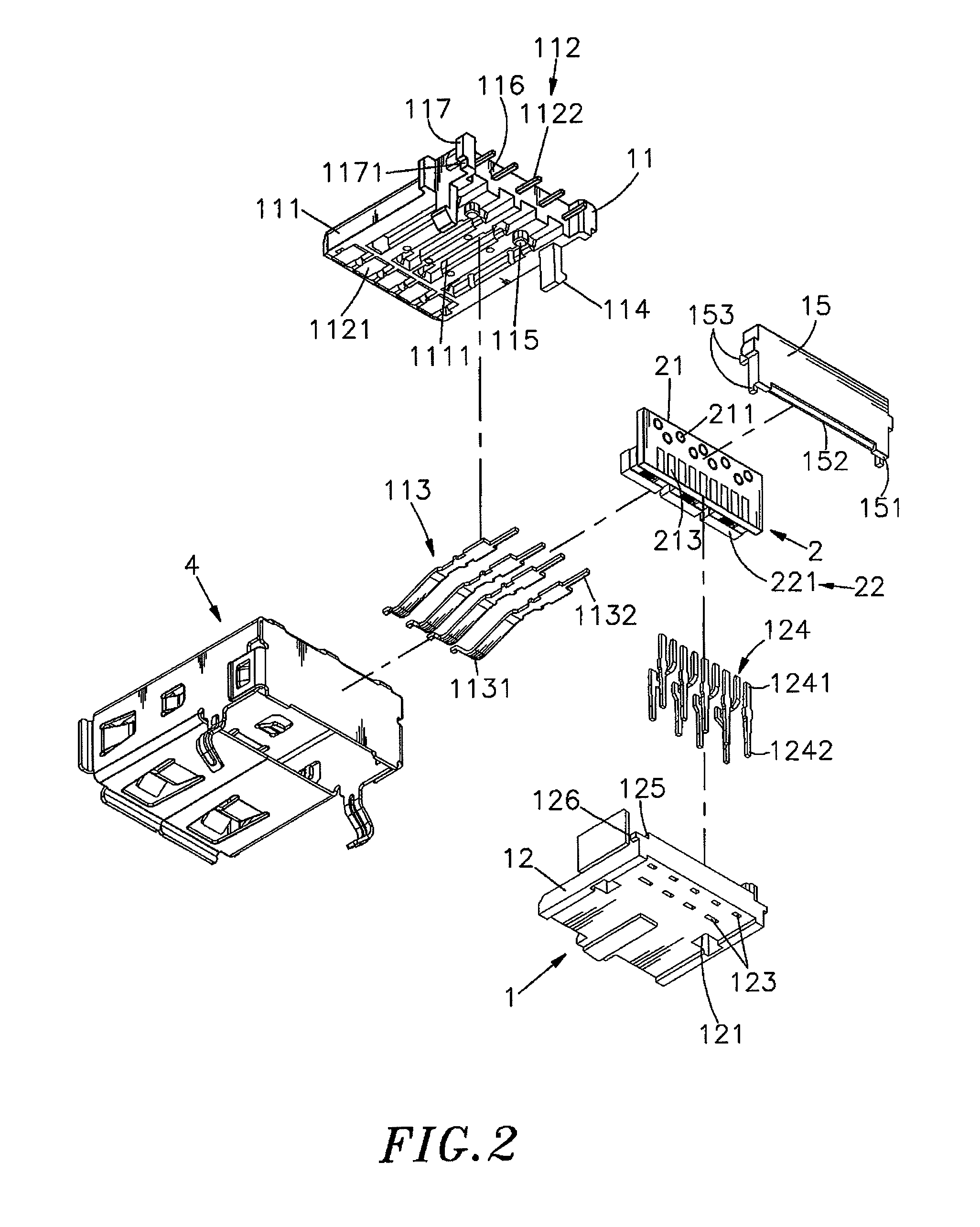
[0027]Referring to FIGS. 1˜4, a USB connector in accordance with a first embodiment of the present invention is shown comprising a connector body 1, a circuit module 2 and a metal shield 4.

[0028]The connector body 1 comprises a first connection port 11 and a bottom positioning member 12 fastened to the bottom side of the first connection port 11. The first connection port 11 comprises a forwardly extending tongue plate 111 having multiple bottom terminal grooves 1111, a set of first conducting terminals 112 mounted in the top side of the tongue plate 111, a set of second conducting terminals 113 mounted in the bottom terminal grooves 1111 of the tongue plate 111. The first conducting terminals 112 and second conducting terminals 113 have the respective front contact portions 1121 or 1131 suspending below the tongue plate 111 and arranged in two rows and the respective rear bonding portions 1122 or 1132 extending out of the rear side of the first connection port 11. The first connect...


PUM


Abstract

A USB connector includes an connector body holding first and second conducting terminals on top and bottom sides of a tongue plate of a first connection port thereof, a bottom positioning member located on the bottom side of the first connection port, an adapter board having first contacts located on the front side for the bonding of rear bonding portions of the first and second conducting terminals and first metal pads located on the rear side thereof for the bonding of the bonding portions of adapter terminals and electronic components electrically connected between the first contacts and the first metal pads, and a rear cover fastened to the rear side of the first connection port and the top side of the bottom positioning member to shield the first and second conducting terminals and the adapter terminals.

Description

BACKGROUND OF THE INVENTION[0001]1. Field of the Invention[0002]The present invention relates to USB connectors and more particularly, to such a USB connector, which has a rear cover fastened to the rear side of the first connection port and the top side of the bottom positioning member to shield the first and second conducting terminals, the adapter terminals and the circuit module, prohibiting them from contacting the outer metal shield to cause a short circuit.[0003]2. Description of the Related Art[0004]Following fast development of modern electronic technology, many different advanced and small-sized electronic devices have been intensively used in our daily life. Nowadays, many people use notebook computer instead of desk computer for the advantage of high mobility. Further, different interface devices shall be used for data and / or signal transmission between a host and different peripheral apparatus, or among different electronic devices. USB (Universal Serial Bus) interface ...

Claims


Application Information

Patent Timeline
Patent Type & Authority Patents(United States)
IPC IPC(8): H01R13/648
CPCH01R13/6581H01R13/719H01R24/62
Inventor CHEN, PO-JUNG
Owner U D ELECTRONIC CORP
Why Eureka
Try Eureka