

Electrically-conductive inorganic coating, method for producing the coating, circuit board, and semiconductor apparatus
a technology of inorganic coating and inorganic coating, which is applied in the direction of resistive material coating, solid-state device coating, metallic material coating process, etc., can solve the problems of low heat resistance of flexible devices, complex process, and organic substances, and achieves low cost, high thermal stability, and low dispersion stability.
- Summary
- Abstract
- Description
- Claims
- Application Information
AI Technical Summary
Benefits of technology
Problems solved by technology
Method used
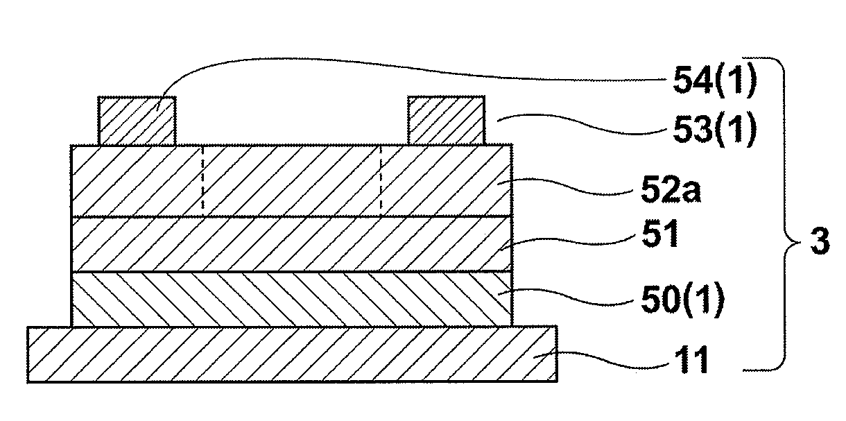
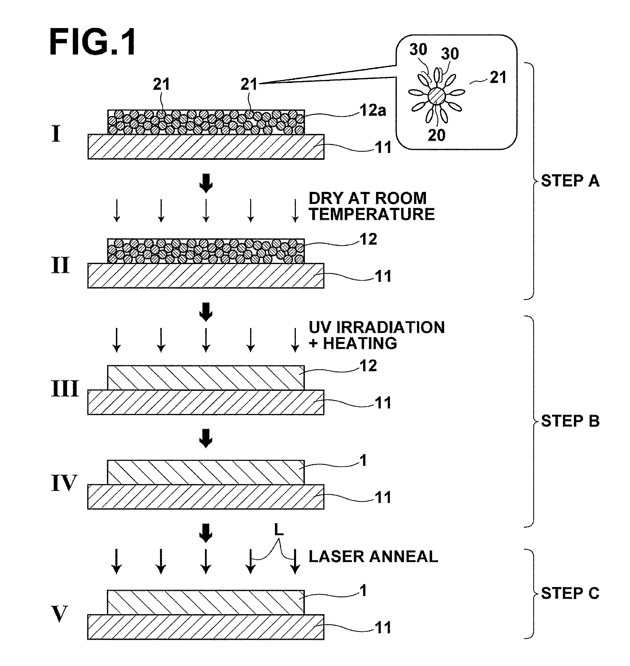
Image

Examples
example 1
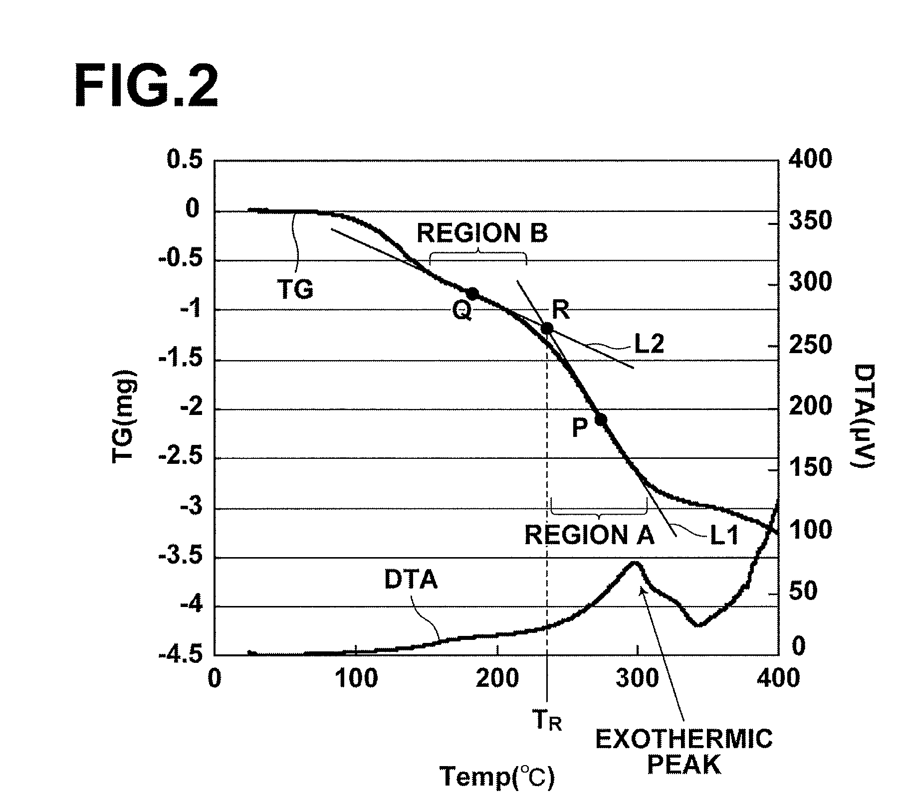
[0101]A silver (Ag) thin film was deposited by using a commercially-available Ag nano paste (hereinafter, referred to as silver paste). As the silver paste, Ag nano paste NPS-J (metal content of 58.6 wt %, average particle diameter of 3 to 7 nm, and viscosity of 9.2 mPa·s), manufactured by Harima Chemicals, Inc., was used (this silver paste contains a dispersant and an organic solvent). The pyrolysis initiation temperature of this silver paste was measured by TG / DTA, and the temperature was 210° C.
[0102]First, this silver paste was applied to a PET (polyethylene terephthalate) film substrate by spin coating at 1000 rpm, and dried at room temperature for 180 minutes. Consequently, a coating precursor that has a thickness of 580 nm was deposited. The sheet resistance value R of the obtained room-temperature-dried coating (coating precursor) exceeded 108 Ω / sq. Further, this room-temperature-dried coating was evaluated by XRD, and only a broad diffraction peak derived from the silver na...
example 2
[0105]In Example 2, a room-temperature-dried silver paste coating (coating precursor) was deposited in a manner similar to Example 1 except that a quartz glass substrate was used in Example 2. Although the substrate used in Example 2 was different from Example 1, the sheet resistance value R of the obtained room-temperature-dried sheet and the result of XRD evaluation were similar to those of Example 1. The sheet resistance value exceeded 108 Ω / sq. Further, in XRD, only a broad diffraction peak derived from the silver nano particles was obtained (A in FIG. 6).
[0106]Next, the room-temperature-dried coating was oxidized in a manner similar to the oxidation in Example 1 except that the irradiation time in Example 2 was 90 minutes, to obtain a silver coating. IR measurement was carried out on the obtained silver coating, and it was confirmed that a peak derived from an organic substance was not present, and that the organic substance or substances had been decomposed (please refer to Ta...
example 3
[0107]Example 3 is similar to Example 2 except that Ag nano metal ink Ag1TeH (metal content of 58 wt %, average particle diameter of 3 to 7 nm, and viscosity of 13 mPa·s), manufactured by ULVAC Materials, Inc., was used as the silver paste. The silver coating was deposited on a quartz substrate in a manner similar to Example 2, and evaluation was carried out in a similar manner (this silver paste contains a dispersant and an organic solvent).
[0108]IR measurement was carried out on the obtained silver coating, and it was confirmed that a peak derived from an organic substance was not present, and that the organic substance or substances had been decomposed (please refer to Table 1). Further, XRD measurement was carried out, and it was confirmed that a sharp diffraction peak derived from silver was obtained, and that the coating had excellent crystalline characteristics. Further, the sheet resistance value R of the silver coating was 2.28 Ω / sq. (please refer to Table 1).
[0109]Next, la...
PUM
| Property | Measurement | Unit |
|---|---|---|
| heat-resistance temperature | aaaaa | aaaaa |
| heat-resistance temperature | aaaaa | aaaaa |
| heat-resistance temperature | aaaaa | aaaaa |
Abstract
Description
Claims
Application Information