
Electrically-conductive inorganic coating, method for producing the coating, circuit board, and semiconductor apparatus

a technology of inorganic coating and inorganic coating, which is applied in the direction of resistive material coating, solid-state device coating, metallic material coating process, etc., can solve the problems of low heat resistance of flexible devices, complex process, and organic substances, and achieves low cost, high thermal stability, and low dispersion stability.

Active Publication Date: 2009-12-03
FUJIFILM CORP
View PDF2 Cites 11 Cited by
  • Summary
  • Abstract
  • Description
  • Claims
  • Application Information

AI Technical Summary

Benefits of technology

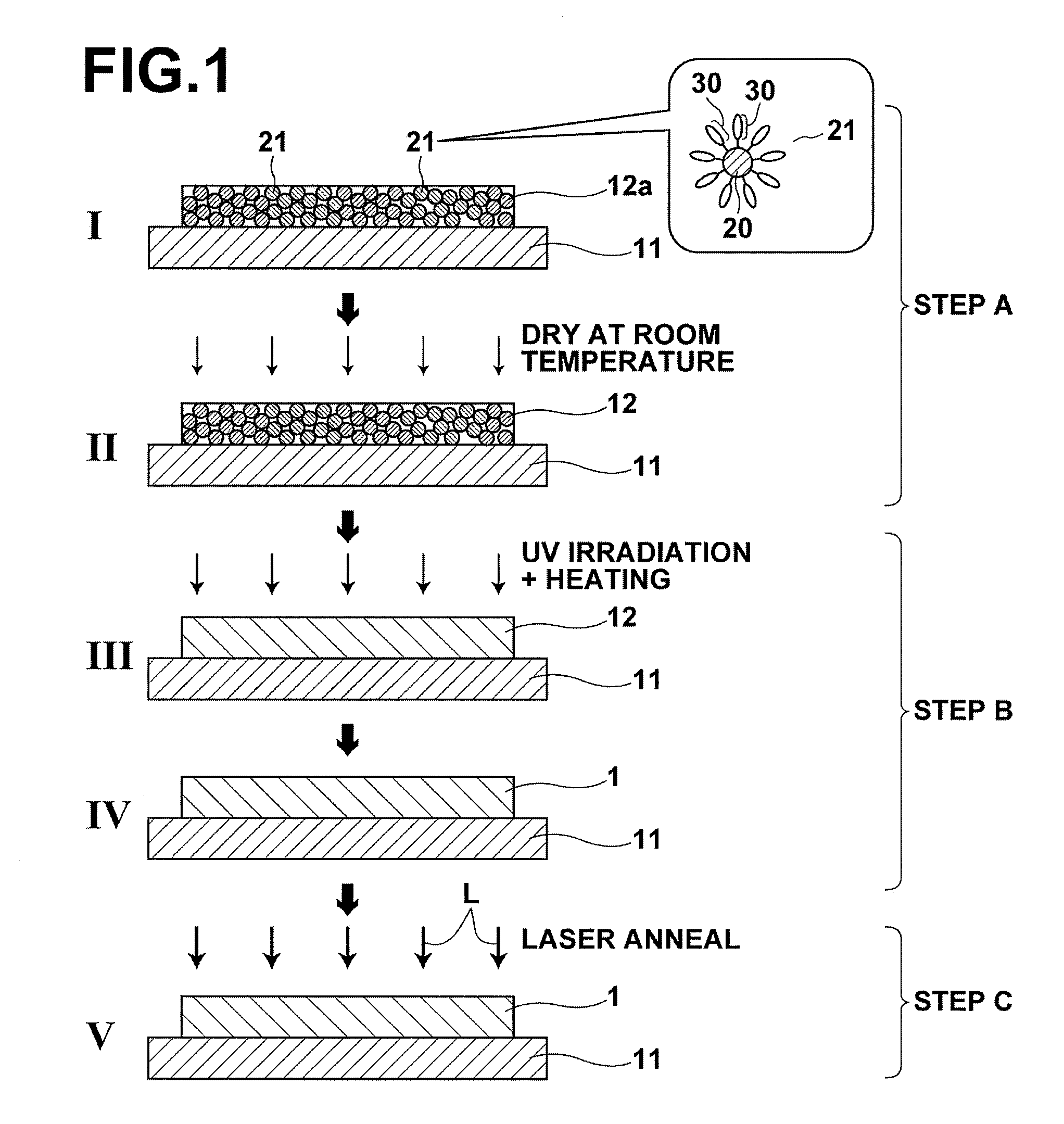
The present invention provides a method for producing a low-resistance electrically-conductive inorganic coating that can be used on a flexible device, such as a circuit board, using a liquid phase method. The method involves depositing a coating precursor containing inorganic particles and an organic component on a substrate, and then oxidizing the coating precursor at a temperature that exceeds the pyrolysis initiation temperature of the organic component but is below the heat-resistance temperature of the substrate. The inorganic particles are dispersed in a resin substrate or other substrate using an inorganic-particle dispersant. The resulting coating has low resistance and can be used in flexible devices. The method can also be applied to a variety of inorganic particles and resin substrates.

Problems solved by technology

However, since the pattern is formed by temporarily depositing a coating onto the entire area of the substrate or the like first and by removing unneeded portion therefrom, the process is complicated and high cost.
However, flexible devices use resin substrates that have lower heat-resistance than the inorganic substrates, such as glass substrate.
However, in the method disclosed in Patent Literature 1, there is a risk that an organic substance, such as the organic solvent in which the ultrafine particles are dispersed and the dispersant that coats the surfaces of the ultrafine-particles, is not decomposed and remains when firing is carried out.
Therefore, it is impossible to obtain an electrically-conductive coating.
However, if a material liquid that does not have efficient dispersion stability is used, metal nanoparticles in the material liquid tend to cohere at a low temperature.
Therefore, when the material liquid is applied in inkjet printing or the like, the metal nanoparticles cohere in the inkjet nozzle and form particles that have diameters on the order of greater than or equal to several tens of micrometers (μm), and clogging of the nozzle tends to occur.
Further, the metal nanoparticles cohere in the vicinity of the nozzle, and that may cause a bad droplet flight condition.
Further, when the particles cohere, the diameters of the cohered particles become varied, in other words, the diameters are not uniform.
Hence, stable production becomes impossible.

Method used


Image

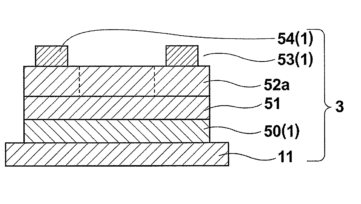
  • Electrically-conductive inorganic coating, method for producing the coating, circuit board, and semiconductor apparatus
  • Electrically-conductive inorganic coating, method for producing the coating, circuit board, and semiconductor apparatus
  • Electrically-conductive inorganic coating, method for producing the coating, circuit board, and semiconductor apparatus

Examples


example 1

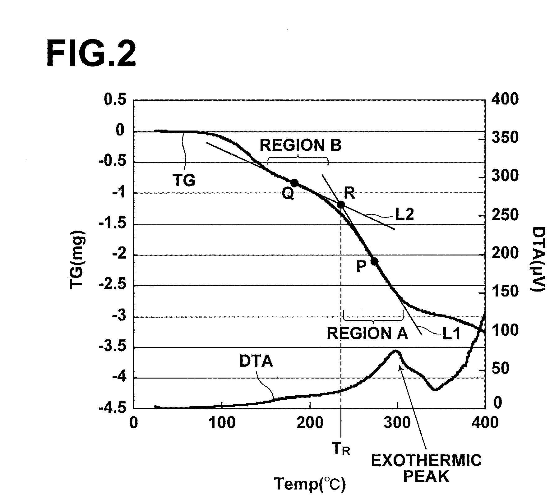
[0101]A silver (Ag) thin film was deposited by using a commercially-available Ag nano paste (hereinafter, referred to as silver paste). As the silver paste, Ag nano paste NPS-J (metal content of 58.6 wt %, average particle diameter of 3 to 7 nm, and viscosity of 9.2 mPa·s), manufactured by Harima Chemicals, Inc., was used (this silver paste contains a dispersant and an organic solvent). The pyrolysis initiation temperature of this silver paste was measured by TG / DTA, and the temperature was 210° C.

[0102]First, this silver paste was applied to a PET (polyethylene terephthalate) film substrate by spin coating at 1000 rpm, and dried at room temperature for 180 minutes. Consequently, a coating precursor that has a thickness of 580 nm was deposited. The sheet resistance value R of the obtained room-temperature-dried coating (coating precursor) exceeded 108 Ω / sq. Further, this room-temperature-dried coating was evaluated by XRD, and only a broad diffraction peak derived from the silver na...

example 2

[0105]In Example 2, a room-temperature-dried silver paste coating (coating precursor) was deposited in a manner similar to Example 1 except that a quartz glass substrate was used in Example 2. Although the substrate used in Example 2 was different from Example 1, the sheet resistance value R of the obtained room-temperature-dried sheet and the result of XRD evaluation were similar to those of Example 1. The sheet resistance value exceeded 108 Ω / sq. Further, in XRD, only a broad diffraction peak derived from the silver nano particles was obtained (A in FIG. 6).

[0106]Next, the room-temperature-dried coating was oxidized in a manner similar to the oxidation in Example 1 except that the irradiation time in Example 2 was 90 minutes, to obtain a silver coating. IR measurement was carried out on the obtained silver coating, and it was confirmed that a peak derived from an organic substance was not present, and that the organic substance or substances had been decomposed (please refer to Ta...

example 3

[0107]Example 3 is similar to Example 2 except that Ag nano metal ink Ag1TeH (metal content of 58 wt %, average particle diameter of 3 to 7 nm, and viscosity of 13 mPa·s), manufactured by ULVAC Materials, Inc., was used as the silver paste. The silver coating was deposited on a quartz substrate in a manner similar to Example 2, and evaluation was carried out in a similar manner (this silver paste contains a dispersant and an organic solvent).

[0108]IR measurement was carried out on the obtained silver coating, and it was confirmed that a peak derived from an organic substance was not present, and that the organic substance or substances had been decomposed (please refer to Table 1). Further, XRD measurement was carried out, and it was confirmed that a sharp diffraction peak derived from silver was obtained, and that the coating had excellent crystalline characteristics. Further, the sheet resistance value R of the silver coating was 2.28 Ω / sq. (please refer to Table 1).

[0109]Next, la...


PUM

PropertyMeasurementUnit
heat-resistance temperatureaaaaaaaaaa

Abstract

A method for producing an electrically-conductive inorganic coating includes depositing, on a substrate, a coating-precursor containing a plurality of inorganic particles and at least one kind of organic component by a liquid-phase method by using a material-liquid containing the inorganic particles and an organic solvent. The inorganic particles are coated with a dispersant binding to the surfaces of the inorganic particles by chemical bonds that can be broken by oxidation. Further, the method includes oxidizing the coating-precursor at a temperature exceeding 100° C., and that is less than or equal to the pyrolysis initiation temperature of an organic component that has the highest pyrolysis initiation temperature among the at least one kind of organic component and less than or equal to the heat-resistance temperature of the substrate, thereby breaking the chemical bonds to eliminate the dispersant from the surfaces, and decomposing the at least one kind of organic component.

Description

BACKGROUND OF THE INVENTION[0001]1. Field of the Invention[0002]The present invention relates to an electrically conductive inorganic coating (thin-film) and a method for producing the electrically conductive inorganic coating. Further, the present invention relates to a circuit board using the electrically conductive inorganic coating and a semiconductor apparatus using the electrically conductive inorganic coating.[0003]2. Description of the Related Art[0004]In recent years, various kinds of flexible devices have been receiving increasing attention. The flexible devices can be applied to various purposes, such as electronic paper (e-paper) and a flexible display. Conventionally, the flexible devices are produced, in a manner similar to production of devices that use glass substrates, mainly by vacuum deposition, such as a sputtering method and a vacuum deposition (evaporation) method, and patterning by photolithography. The conventional methods have excellent regeneration characte...

Claims


Application Information

Patent Timeline
Patent Type & Authority Applications(United States)
IPC IPC(8): H01L23/48B05D5/12B05D3/06H01L21/321H05K1/02
CPCC23C18/08C23C18/1216H01L2924/0002C23C18/1233C23C18/127C23C18/1279C23C18/1295C23C18/14H01L21/4867H01L23/4985H01L29/7869H01L2924/12044H05K1/0393H05K1/092H05K3/105H05K3/1241H05K3/1283H05K2201/0224H05K2203/107H05K2203/1131H05K2203/1163H01L2924/00C23C18/143C23C18/145
Inventor HIGASHI, KOHEITANAKA, ATSUSHI
Owner FUJIFILM CORP
Learn More