Electric machine with stepped winding structure

a technology of electric machines and winding wounds, which is applied in the direction of windings, dynamo-electric components, synchronous machines with stationary armatures and rotating magnets, etc., can solve the problems of reducing the power efficiency of the system operated with the electromagnet, reducing thermal conductivity, and empty spaces at the sides of windings, so as to increase the efficiency of such drives and high slot fill factor

Inactive Publication Date: 2012-02-14
SIEMENS AG
View PDF8 Cites 14 Cited by
  • Summary
  • Abstract
  • Description
  • Claims
  • Application Information

AI Technical Summary

Benefits of technology

[0008]Advantageously, filling of the slots is improved with the winding structure according to the invention. The improved slot fill factor improves the magnetic efficiency while at the same time reducing the thermal resistance. This results in an overall increase in the efficiency of the electric machine.
[0015]The electric machine according to the invention may be designed as a transverse flux machine or as a cylindrical linear motor. The annular coils with a high slot fill factor can significantly increase the efficiency of such drives.

Problems solved by technology

This results in empty spaces in the regions of the bottom and top layers and at the sides of the windings.
The empty spaces result in reduced thermal conductivity and therefore to a lower power efficiency of the system operated with the electromagnet, e.g. a cylindrical linear motor.
No solutions for reducing the thermal resistance have been implemented to date.

Method used


Image

  • Electric machine with stepped winding structure
  • Electric machine with stepped winding structure
  • Electric machine with stepped winding structure

Examples


Embodiment Construction

[0026]Throughout all the Figures, same or corresponding elements are generally indicated by same reference numerals. These depicted embodiments are to be understood as illustrative of the invention and not as limiting in any way. It should also be understood that the drawings are not necessarily to scale and that the embodiments are sometimes illustrated by graphic symbols, phantom lines, diagrammatic representations and fragmentary views. In certain instances, details which are not necessary for an understanding of the present invention or which render other details difficult to perceive may have been omitted.

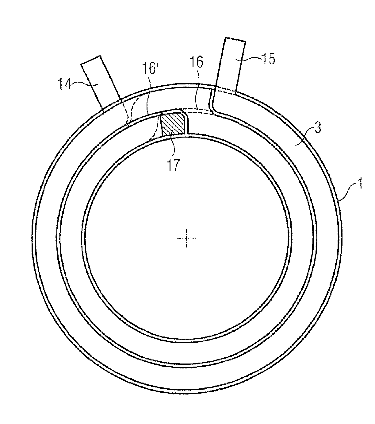
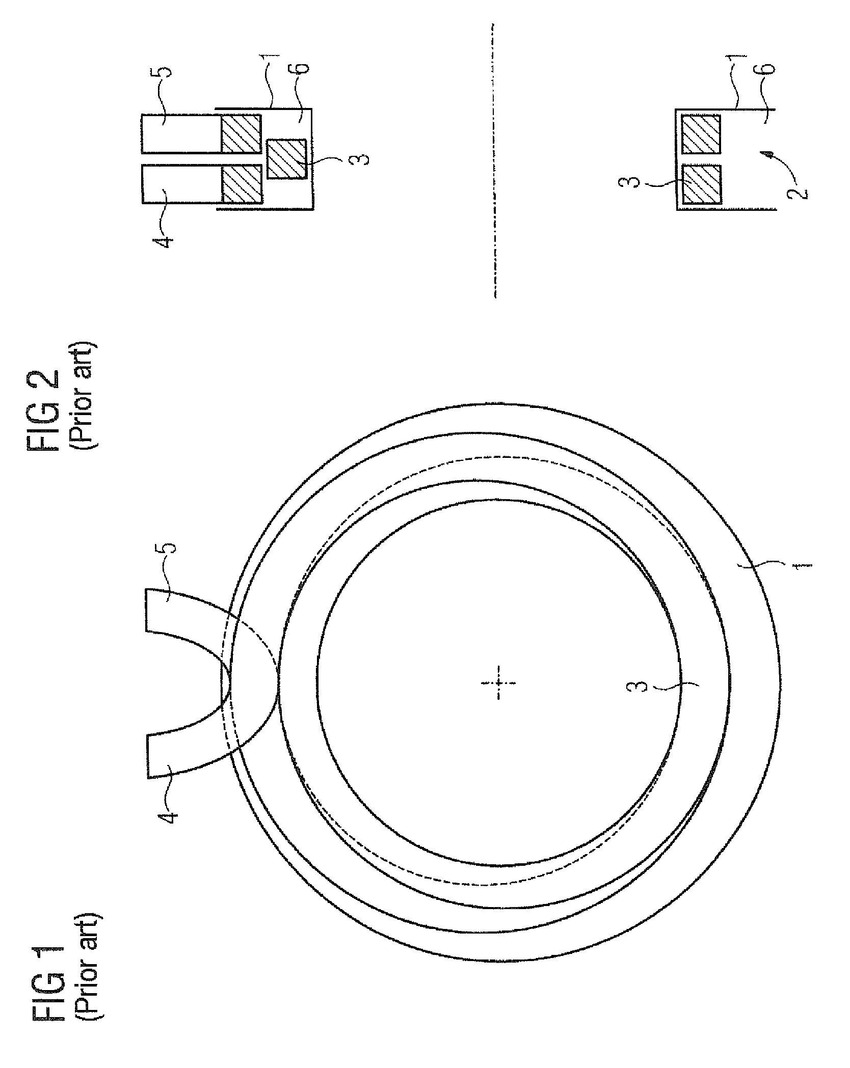
[0027]Turning now to the drawing, and in particular to FIGS. 1 and 2, there is shown a conventionally wound flat-wire coil for an electric machine. The coil has a coil body 1 which has a radially outwardly pointing slot 2. A flat wire 3 with a square or rectangular cross section is wound into the slot 2. The depth of the slot is approximately twice the thickness of the flat wi...


PUM


Abstract

An electric machine for direct drive or braking applications with coils providing improved power efficiency and heat transfer is disclosed. The electric machine has a coil body and a winding with a plurality of turns wound on the coil body. Each of the various turns is located in a separate plane. Respective end sections of two different turns are connected by a connecting element, with a major directional component of the connecting element being oriented in an axial direction perpendicular to the plane of one of the two turns. Axially adjacent turns can thereby be connected to one another together. This arrangement reduces or eliminates empty spaces in the slots, particularly when the turns are made from flat wire.

Description

CROSS-REFERENCES TO RELATED APPLICATIONS[0001]This application claims the priority of European Patent Application, Serial No. EP 08013097, filed Jul. 21, 2008, pursuant to 35 U.S.C. 119(a)-(d), the content of which is incorporated herein by reference in its entirety as if fully set forth herein.BACKGROUND OF THE INVENTION[0002]The present invention relates to an electric machine with a coil body and a multi-turn winding wound on the coil body. In particular, the present invention relates to a transverse flux machine or a cylindrical linear motor.[0003]The following discussion of related art is provided to assist the reader in understanding the advantages of the invention, and is not to be construed as an admission that this related art is prior art to this invention.[0004]When coils for electromagnets are manufactured, a wire is usually wound helically in one layer and spirally above one another in a plurality of layers. This results in empty spaces in the regions of the bottom and ...

Claims


Application Information

Patent Timeline
Patent Type & Authority Patents(United States)
IPC IPC(8): H02K21/00H02K21/24
CPCH02K3/18
Inventor VOLLMER, ROLF
Owner SIEMENS AG
Why Eureka
Try Eureka