Eureka AIR delivers breakthrough ideas for toughest innovation challenges, trusted by R&D personnel around the world.

Active thermal management system and method for transmissions

a technology of transmission fluid and thermal management system, which is applied in the direction of gearing details, machines/engines, instruments, etc., can solve the problem that vehicles that are not used for heavy duty towing applications will rarely reach the optimal transmission fluid temperature, and achieve the effect of reducing the fluid temperatur

Active Publication Date: 2012-02-14
GM GLOBAL TECH OPERATIONS LLC
View PDF2 Cites 17 Cited by
  • Summary
  • Abstract
  • Description
  • Claims
  • Application Information

AI Technical Summary

Benefits of technology

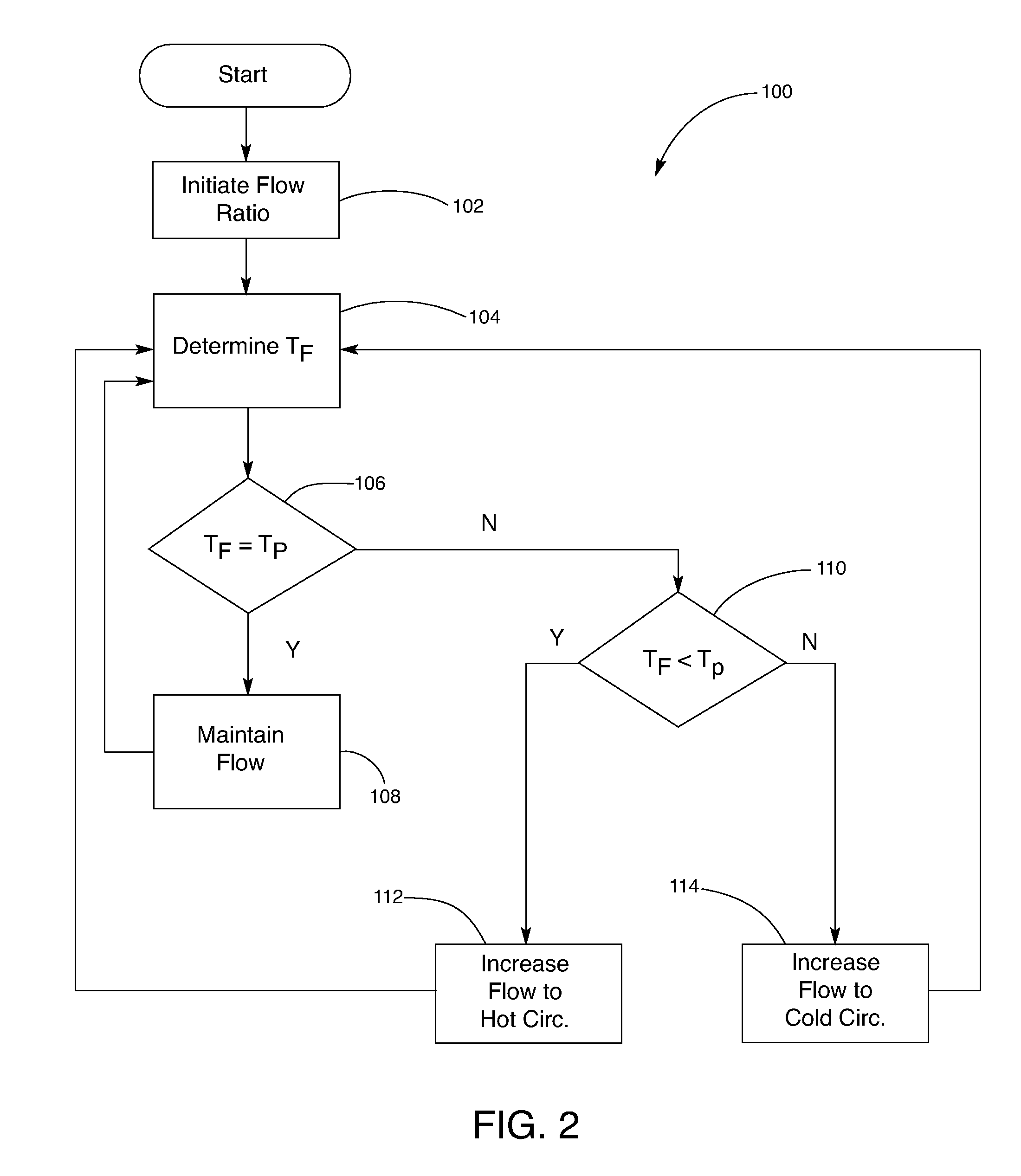
[0004]Transmission fluid below a calibrated or predetermined temperature is directed by the control valve to a heating circuit where it is warmed to the desired temperature. As fluid temperature exceeds the desired limit, the control valve begins to redirect the transmission fluid from the heating circuit to a cooling circuit, which reduces fluid temperature. In an exemplary embodiment, the control valve modulates flow simultaneously between both circuits, allowing sustained operation at, or very near, the calibrated or desired transmission fluid temperature.

Problems solved by technology

Vehicles which are not used for heavy duty towing applications will rarely reach optimum transmission fluid temperature.

Method used


Image

  • Active thermal management system and method for transmissions
  • Active thermal management system and method for transmissions
  • Active thermal management system and method for transmissions

Examples


Embodiment Construction

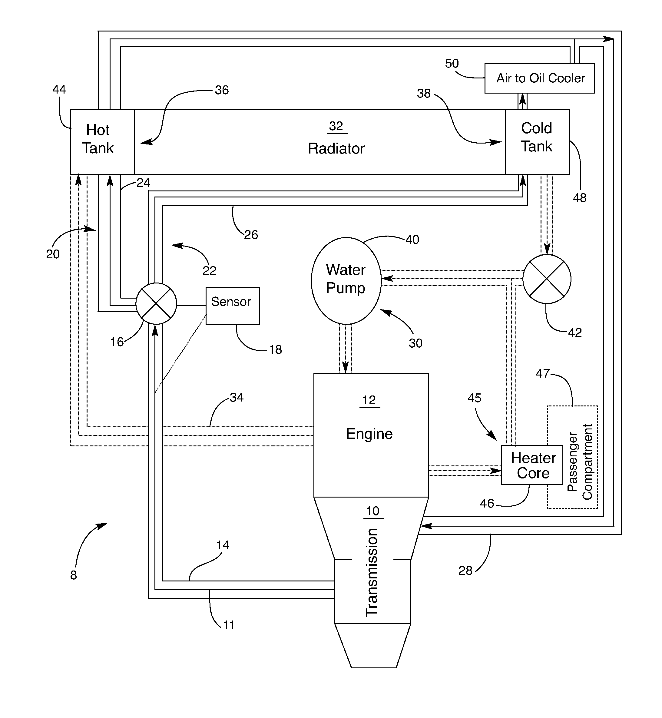
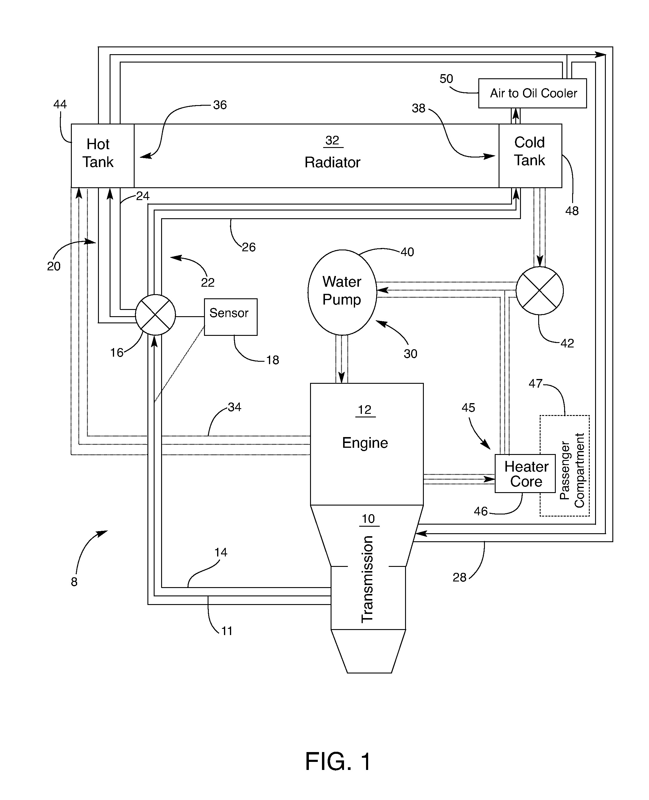
[0010]Referring to the drawings, FIG. 1 schematically shows an active thermal management system 8 for a transmission 10 operating in a vehicle (not shown) with a vehicular engine 12. Internal pressure of the transmission 10 causes transmission fluid 11 to flow out of transmission 10 through a fluid conduit 14 to a valve 16. Pressure sources within the transmission will be recognized by those in the art, but could include, without limitation: a gear pump, a torque converter pump, a separate oil pump, et cetera. Control systems for the active thermal management system include a sensor configured to measure a material property of the transmission fluid and an actuator configured to manipulate the valve. The control system in the embodiment depicted includes device 18 that is both the sensor and the actuator. The device 18 is placed in thermal communication with the transmission fluid, and is used to measure transmission fluid temperature. Device 18 is operatively connected to valve 16,...


PUM


Abstract

An active thermal management system and method for selectively warming and cooling transmission fluid in a transmission usable with a vehicular engine is provided. The active thermal management system includes a thermal sensor which measures transmission fluid temperature and signals a valve to selectively communicate transmission fluid flow into one or more discrete fluid circuits.

Description

TECHNICAL FIELD[0001]This invention relates to a thermal management system and method for transmission fluid conditioning used in vehicular applications. Transmission fluid is heated or cooled depending upon specific vehicle applications and current driving needs in order to improve drivability, efficiency, and durability.BACKGROUND OF THE INVENTION[0002]To operate at optimal levels, vehicular transmissions may require that the transmission fluid be heated above, or cooled below, normal-use operating temperatures. Under high-load conditions, such as while towing significant weight, transmission fluid may become over-heated and require cooling in order to avoid adverse effects on driving conditions or durability of the transmission system itself. Under normal driving conditions, transmission fluid may need to be warmed. Warming transmission fluid reduces spin loss, which increases efficiency of the transmission and, in turn, increases overall vehicle fuel efficiency. Vehicles which a...

Claims


Application Information

Patent Timeline
Patent Type & Authority Patents(United States)
IPC IPC(8): G06F17/00B60K17/00B60W10/04
CPCF16H57/0413F01P2060/045Y10T477/688F01P2060/08
Inventor LOPEZ, RICHARD J
Owner GM GLOBAL TECH OPERATIONS LLC
Why Eureka
Eureka Blog
Learn More