

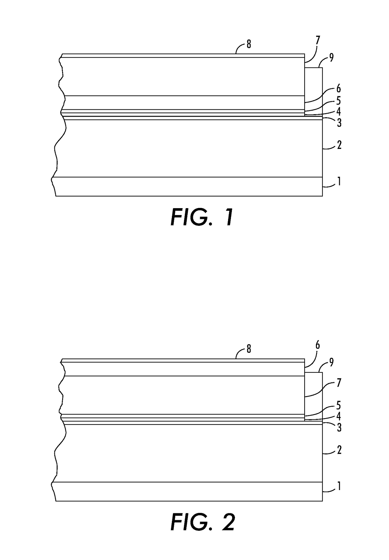
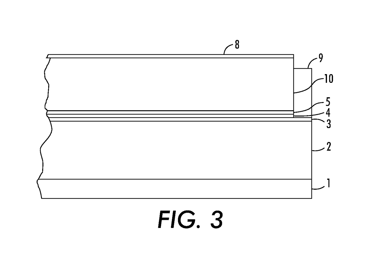
Imaging members for ink-based digital printing comprising structured organic films
a technology of structured organic films and inks, applied in the direction of instruments, electrographic process apparatuses, corona discharge, etc., can solve the problems of limited high background printing, and general limitation of liquid ink-based printing systems
- Summary
- Abstract
- Description
- Claims
- Application Information
AI Technical Summary
Benefits of technology
Problems solved by technology
Method used
Image

Examples
example 1
Type 2 SOF
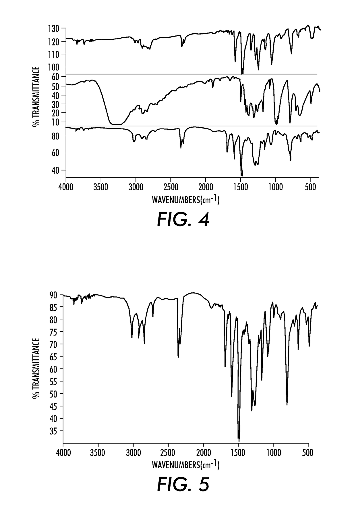
[0357](Action A) Preparation of the liquid containing reaction mixture. The following were combined: the building block benzene-1,4-dimethanol [segment=p-xylyl; Fg=hydroxyl (—OH); (0.47 g, 3.4 mmol)] and a second building block N4,N4,N4′,N4′-tetrakis(4-(methoxymethyl)phenyl)biphenyl-4,4′-diamine [segment=N4,N4,N4′,N4′-tetra-p-tolylbiphenyl-4,4′-diamine; Fg=methoxy ether (—OCH3); (1.12 g, 1.7 mmol)], and 17.9 g of 1-methoxy-2-propanol. The mixture was shaken and heated to 60° C. until a homogenous solution resulted. Upon cooling to room temperature, the solution was filtered through a 0.45 micron PTFE membrane. To the filtered solution was added an acid catalyst delivered as 0.31 g of a 10 wt % solution of p-toluenesulfonic acid in 1-methoxy-2-propanol to yield the liquid containing reaction mixture.
[0358](Action B) Deposition of reaction mixture as a wet film. The reaction mixture was applied to the reflective side of a metalized (TiZr) MYLAR™ substrate using a constant ve...
example 2
Control Experiment Wherein the Building Block benzene-1,4-dimethanol was not Included
[0365](Action A) Preparation of the liquid containing reaction mixture. The following were combined: the building block N4,N4,N4′,N4′-tetrakis(4-(methoxymethyl)phenyl)biphenyl-4,4′-diamine [segment=N4,N4,N4′,N4′-tetra-p-tolylbiphenyl-4,4′-diamine; Fg=methoxy ether (—OCH3); (1.12 g, 1.7 mmol)], and 17.9 g of 1-methoxy-2-propanol. The mixture was shaken and heated to 60° C. until a homogenous solution resulted. Upon cooling to room temperature, the solution was filtered through a 0.45 micron PTFE membrane. To the filtered solution was added an acid catalyst delivered as 0.31 g of a 10 wt % solution of p-toluenesulfonic acid in 1-methoxy-2-propanol to yield the liquid containing reaction mixture.
[0366](Action B) Deposition of reaction mixture as a wet film. The reaction mixture was applied to the reflective side of a metalized (TiZr) MYLAR™ substrate using a constant velocity draw down coater outfitted...
example 3
Control Experiment Wherein the Building Block N4,N4,N4′,N4′-tetrakis(4-(methoxymethyl)phenyl)biphenyl-4,4′-diamine was not Included
[0368](Action A) Preparation of the liquid containing reaction mixture. The following were combined: the building block benzene-1,4-dimethanol [segment=p-xylyl; Fg=hydroxyl (—OH); (0.47 g, 3.4 mmol)] and 17.9 g of 1-methoxy-2-propanol. The mixture was shaken and heated to 60° C. until a homogenous solution resulted. Upon cooling to room temperature, the solution was filtered through a 0.45 micron PTFE membrane. To the filtered solution was added an acid catalyst delivered as 0.31 g of a 10 wt % solution of p-toluenesulfonic acid in 1-methoxy-2-propanol to yield the liquid containing reaction mixture.
[0369](Action B) Deposition of reaction mixture as a wet film. The reaction mixture was applied to the reflective side of a metalized (TiZr) MYLAR™ substrate using a constant velocity draw down coater outfitted with a bird bar having an 8 mil gap.
[0370](Actio...
PUM
 Abstract
Description
Claims
Application Information