Mold for forming cast rods, casting apparatus, and production method of cast rods

a casting apparatus and casting technology, applied in the direction of manufacturing tools, moulding apparatus, foundry patterns, etc., can solve the problems of mold breakage, adversely affecting the stability of film formation, and the inability to remove cast silicon from the mold, so as to improve the efficiency and yield of casting rod production.

Inactive Publication Date: 2012-02-28
PANASONIC CORP
View PDF11 Cites 1 Cited by
  • Summary
  • Abstract
  • Description
  • Claims
  • Application Information

AI Technical Summary

Benefits of technology

[0020]In order to solve the above-discussed problems, an object of the present invention is to provide a mold for forming cast rods and a casting apparatus using the same, the mold capable of being used repeatedly in producing cast rods made of a material that expands when solidified as well as of capable of improving the efficiency and the yield in producing the cast rods.
[0021]Another object of the present invention is to provide a production method of cast rods for efficiently producing cast rods made of a material that expands when solidified.

Problems solved by technology

However, the continuous supply of a material for forming a thin film involves possibilities that the temperature of the evaporation source and the evaporation rate may fluctuate, adversely affecting the stability of the film formation.
This results in various problems such as impossibility of removal of the cast silicon from the mold and breakage of the mold due to the stress during solidification.
Even if the breakage of the mold is avoided, there is another problem in which the cast rod of silicon is broken inside the mold, since the cast article is a rod-shaped member (a cast rod) whose strength in the direction orthogonal to the longitudinal direction (i.e., in the diameter direction) is not strong.
However, the integrated mold as disclosed in Patent Document 1 is characterized by producing an ingot having an increased base area and a reduced height, and therefore is not suitable for producing a cast rod.
Further, in the case of the integrated mold, in general, it is necessary to destroy the mold to remove the cast article therefrom.
This makes the recycling of the mold impossible, making it difficult to reduce the production costs of cast articles.
However, the mold repeatedly undergoes stress associated with expansion during solidification, and thus the member for securing the mold and the like are easy to break, and the repeated use of the mold is difficult.
Moreover, none of the assembled molds as disclosed in Patent Documents 2 to 4 are designed for producing a cast rod.
If a cast rod is produced with the use of a material that expands when solidified, such as silicon, the cast rod may be broken inside the mold, reducing the yield.
Such a mold for continuous casting is not suitable for producing a cast rod having a large length as compared with the width (diameter).

Method used


Image

  • Mold for forming cast rods, casting apparatus, and production method of cast rods
  • Mold for forming cast rods, casting apparatus, and production method of cast rods
  • Mold for forming cast rods, casting apparatus, and production method of cast rods

Examples


Embodiment Construction

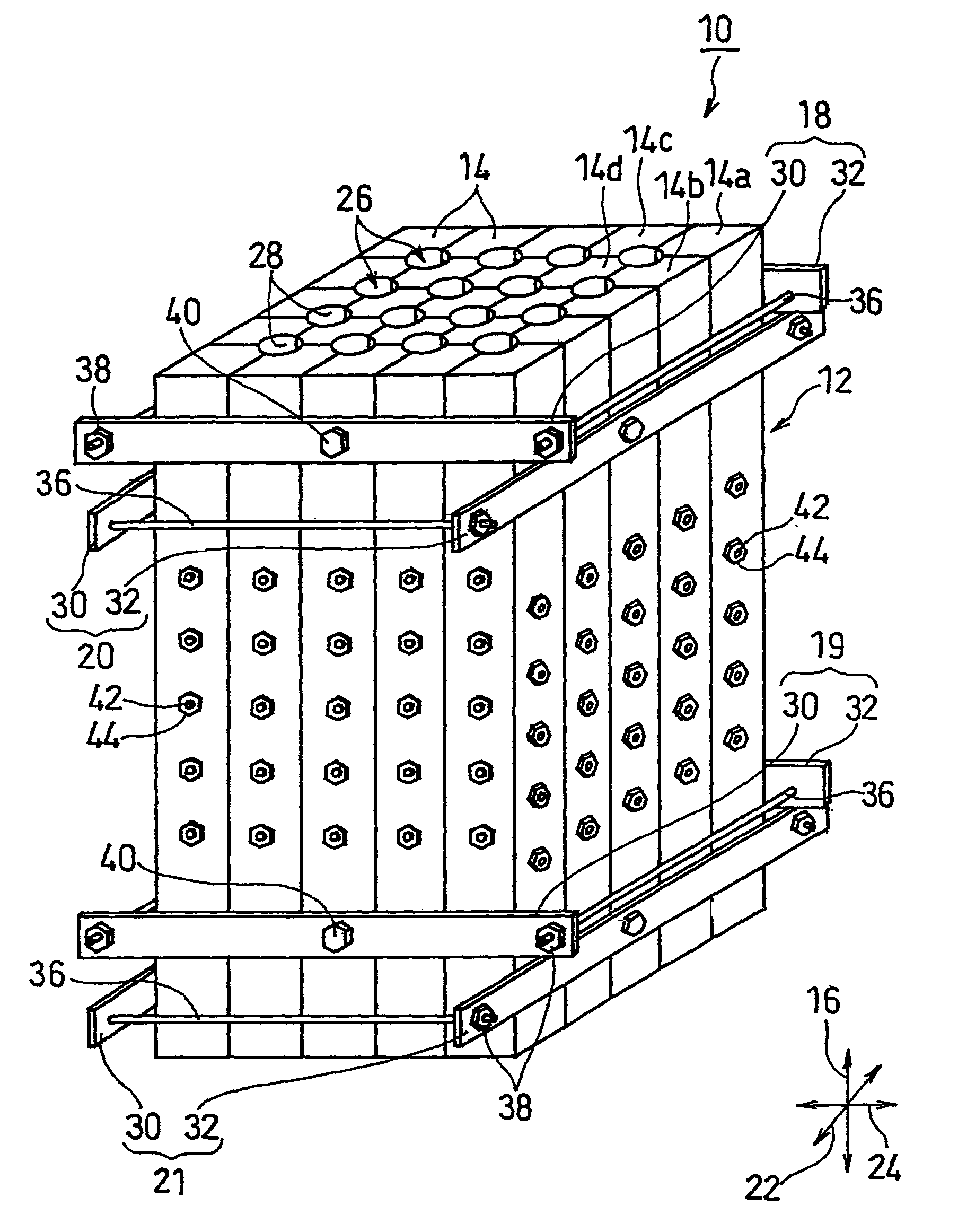
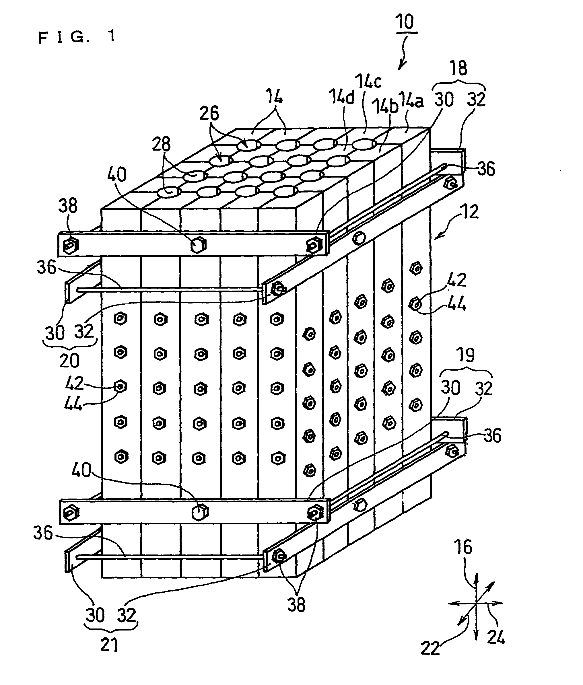
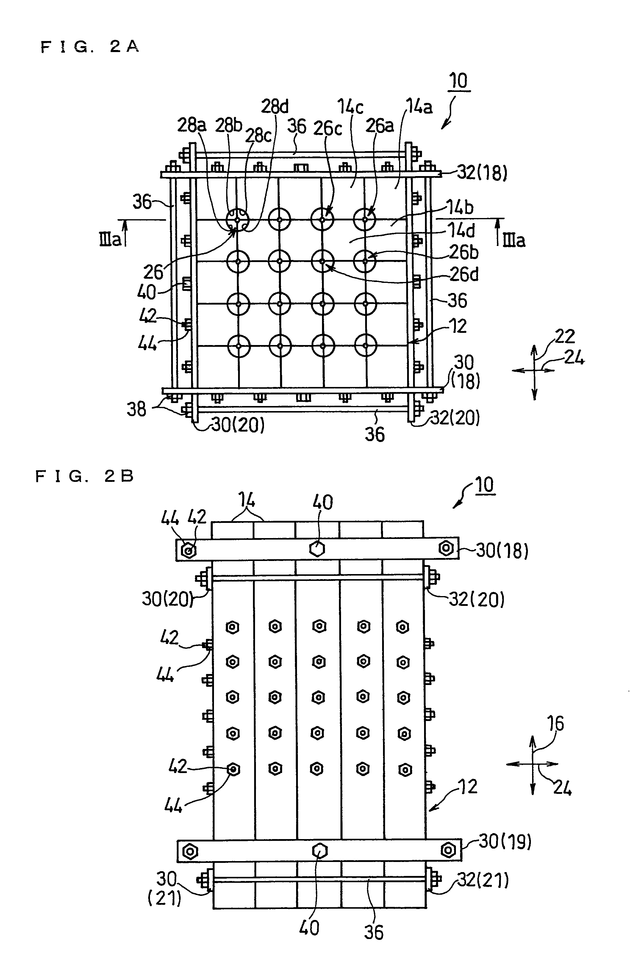
[0050]FIG. 1 is a perspective view illustrating an embodiment of the mold for forming cast rods of the present invention. FIG. 2A is a plan view of FIG. 1; FIG. 2B is a front view of FIG. 1; FIG. 2C is a right-side view of FIG. 1; and FIG. 2D is a bottom view of FIG. 1. FIG. 3A is a IIIa-IIIa sectional view of FIG. 2A and FIG. 2C, and FIG. 3B is a partially enlarged view of FIG. 3A. FIG. 4 is a plan view illustrating the state in which the segments constituting a segment assembly illustrated in FIG. 1 are spaced apart from each other in directions orthogonal to the longitudinal direction of each segment.

[0051]It should be noted that in the following description regarding the mold for forming cast rods and the casting apparatus, the description referring to the direction is based on the direction when the mold or the casting apparatus is placed horizontally, and specifically, based on the directional arrow shown in each figure.

[0052]With reference to FIG. 1 and FIGS. 2A to 2D, a mold...


PUM

PropertyMeasurementUnit
decomposition pointaaaaaaaaaa
thicknessaaaaaaaaaa
lengthaaaaaaaaaa

Abstract

Disclosed is a mold 10 for forming cast rods including: a segment assembly 12 including a plurality of segments 14 being placed side by side, and a plurality of cavities 26 extending along a longitudinal direction 16; and clamping means (18 to 21) for clamping the segment assembly 12 in directions orthogonal to the longitudinal direction 16. The mold 10 has one or more cavity-forming portions 28 each forming a part of one of the peripheral surfaces of the cavities 26. Each cavity 26 is formed by a combination of two or more segments 14, and at least one of the plurality of segments 14 has two or more cavity-forming portions 28.

Description

RELATED APPLICATIONS[0001]This application claims the benefit of U.S. Provisional Application No. 61 / 104,413, filed on Oct. 10, 2008, the disclosure of which Application is incorporated by reference herein.FIELD OF THE INVENTION[0002]The present invention relates to a mold and a casting apparatus for producing cast rods, and a production method of cast rods.BACKGROUND OF THE INVENTION[0003]In recent years, for producing various devices, thin film formation technologies have been widely employed. For example, for solar cells and lithium ion batteries, there has been attempted to use silicon thin films. Such use of thin films is important not only in view of improvement in functionality and reduction in size of devices but also in view of conservation of global environment, for example, conservation of resources, reduction in power consumption, and the like. Under these circumstances, the improvement in productivity and stability of thin film formation and the reduction in costs have ...

Claims


Application Information

Patent Timeline
Patent Type & Authority Patents(United States)
IPC IPC(8): B22D23/00B22D33/04B22C9/20B29C39/26
CPCB22C9/061B22C9/22C01B33/02
Inventor HONDA, KAZUYOSHIKAMIYAMA, YUMASHINOKAWA, YASUHARU
Owner PANASONIC CORP
Why Eureka
Try Eureka