Air purification system, method for purifying air inside a structure

a technology of air purification system and air purification method, which is applied in the direction of lighting and heating apparatus, light source combination, separation process, etc., can solve the problem that human beings present in the neighborhood of the purifier may be exposed to an unacceptable level of uv radiation, and achieve the effect of increasing the capacity for removing contaminants from the air, easy and reliabl

Inactive Publication Date: 2012-02-28
KONINKLIJKE PHILIPS ELECTRONICS NV
View PDF15 Cites 10 Cited by
  • Summary
  • Abstract
  • Description
  • Claims
  • Application Information

AI Technical Summary

Benefits of technology

[0011]Another preferred embodiment of the air purification system according to the invention is characterized in that the first screen is at least partially coated with a photo-catalytic material at a surface facing the first radiation source, which increases the capacity for removal of contaminants from the air.
[0013]Another preferred embodiment of the air purification system according to the invention is characterized in that the system further comprises a second radiation source for generating visible light, which allows the user to independently control the air purification and the general lighting function.
[0015]According to the invention, a method for purifying air in a structure using an air purification system comprises the following steps: providing the air purification system inside a structure, adjusting the distance between the air purification system and a ceiling of the structure in order to position the imaginary horizontal plane at eye level of a human being or higher, adjusting the second screen with respect to the first radiation source in order to direct a beam of UV radiation generated by the first radiation source towards a ceiling and / or at least one wall of the structure, and the beam of UV radiation having a angle α with the imaginary horizontal plane such that the UV rays reflect at least two times with the ceiling and / or the at least one wall before being radiated towards the space below the imaginary horizontal plane. This method allows purification of the air inside the structure without exposing the human beings inside the structure to an unacceptable level of UV-B and / or UV-C radiation.
[0016]Another preferred embodiment of the method for purifying air in a structure is characterized in that in the step of adjusting the second screen with respect to the first radiation source, the beam of UV radiation has an angle α with the imaginary horizontal plane such that the UV rays reflect at least a first time with the at least one wall and at least a second time with the ceiling before being radiated towards the space below the imaginary horizontal plane. This method allows a further reduction of the amount of UV-B and / or UV-C radiation that is radiated to the space below the imaginary horizontal plane.
[0017]Another preferred embodiment of the method for purifying air in a structure is characterized in that the method further comprises the step of providing at least a part of the ceiling and / or the wall with a photo-catalytic material. Another preferred embodiment of the method for purifying air in a structure is characterized in that the photo-catalytic material is provided on the inner wall of cavities provided in the ceiling. As a result, the capacity for removal of contaminants from the air is increased and at the same time the reflection of UV-B and / or UV-C radiation by the ceiling to the lower part of the room is decreased.
[0018]Another preferred embodiment of the method for purifying air in a structure is characterized in that that the adjustment of the second screen with respect to the first radiation source is done according to a table provided with the air purification system showing the relation between said adjustment and the distance between the air purification system and the ceiling as well as with the distance between the air purification system and the at least one wall. The table allows an easy and reliable installation of the air purification system inside the structure.

Problems solved by technology

It is a disadvantage of the air purifier according to the prior art that human beings present in the neighborhood of the purifier may be exposed to an unacceptable level of UV radiation.

Method used


Image

  • Air purification system, method for purifying air inside a structure
  • Air purification system, method for purifying air inside a structure
  • Air purification system, method for purifying air inside a structure

Examples


Embodiment Construction

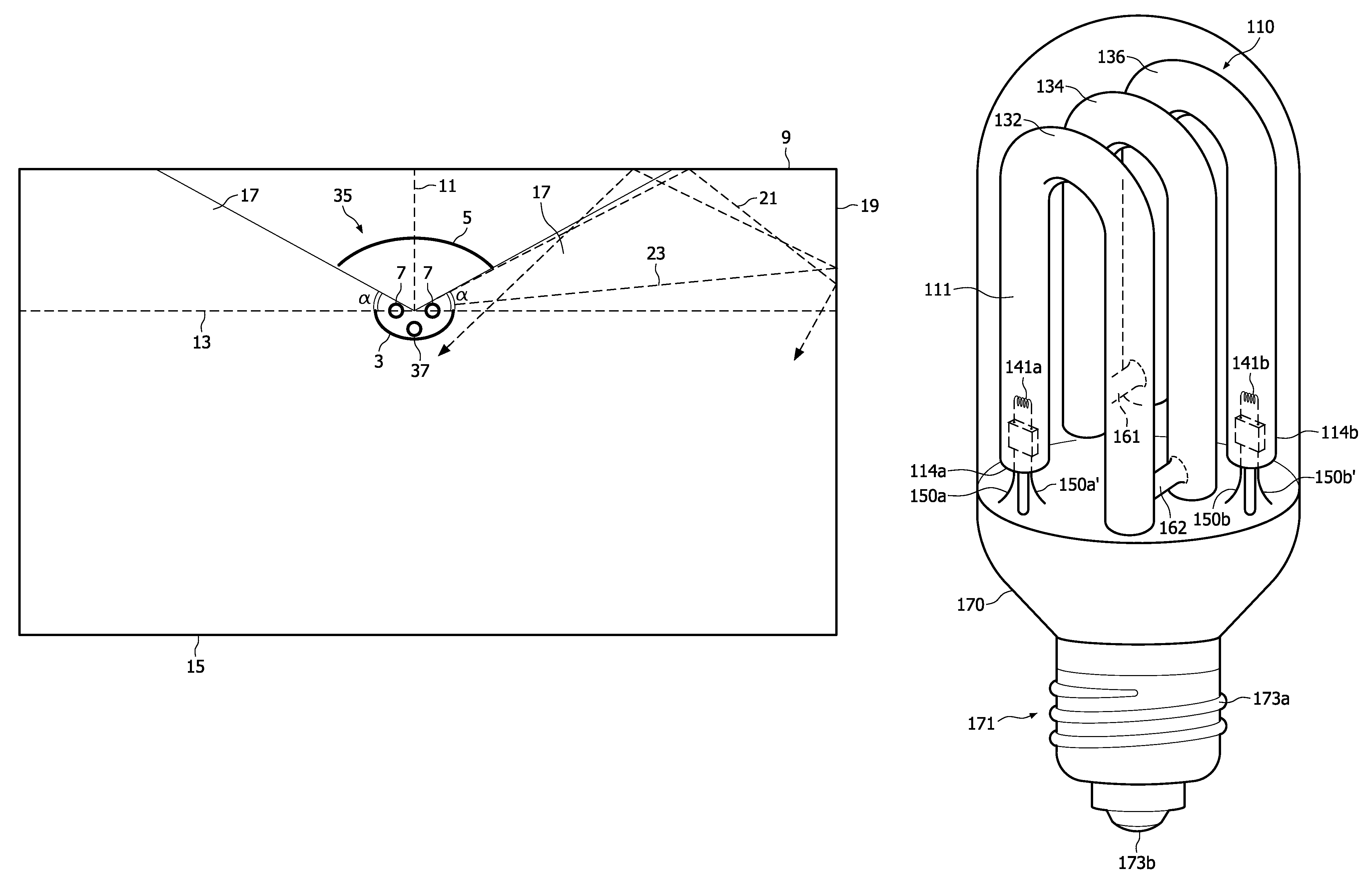
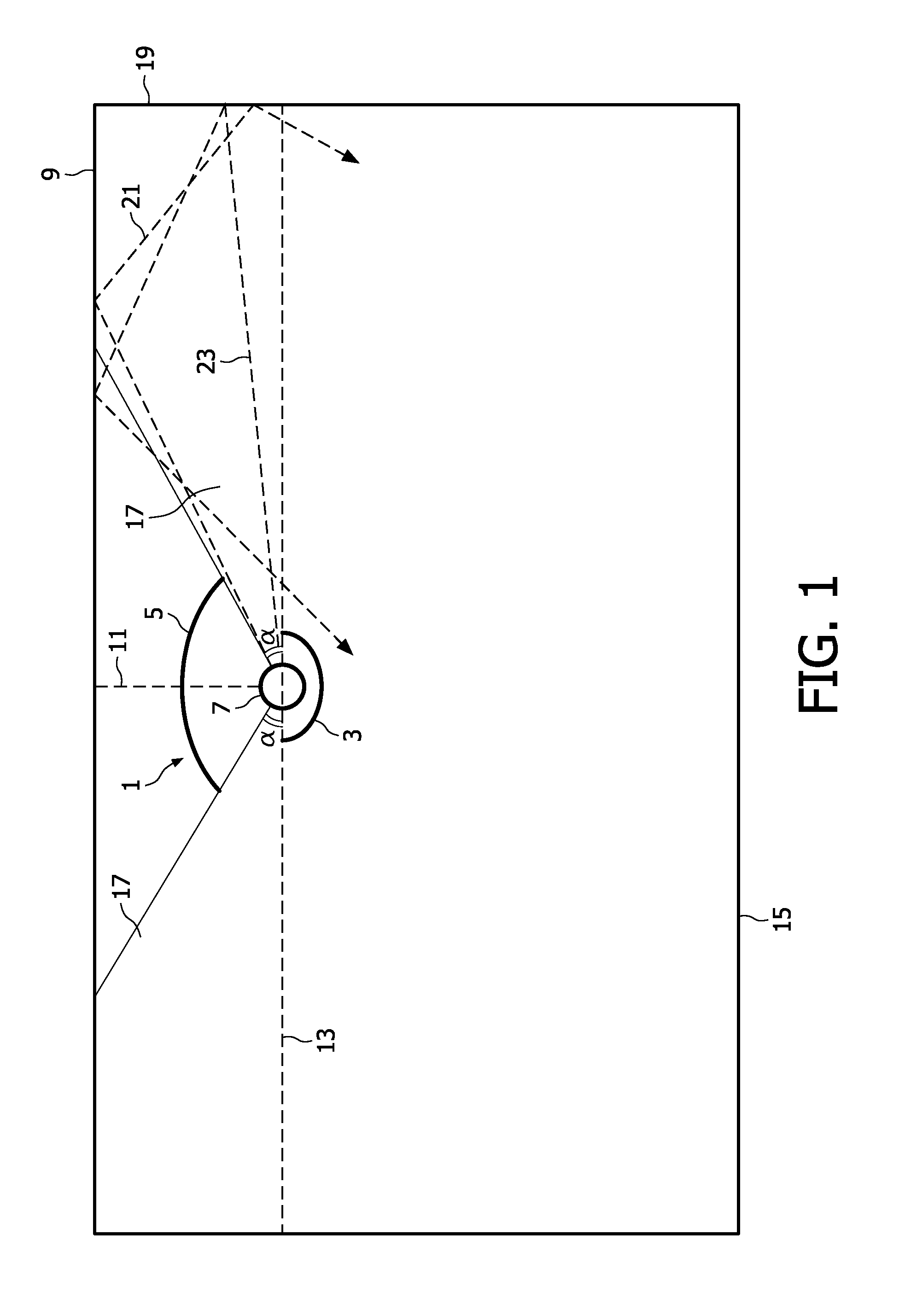
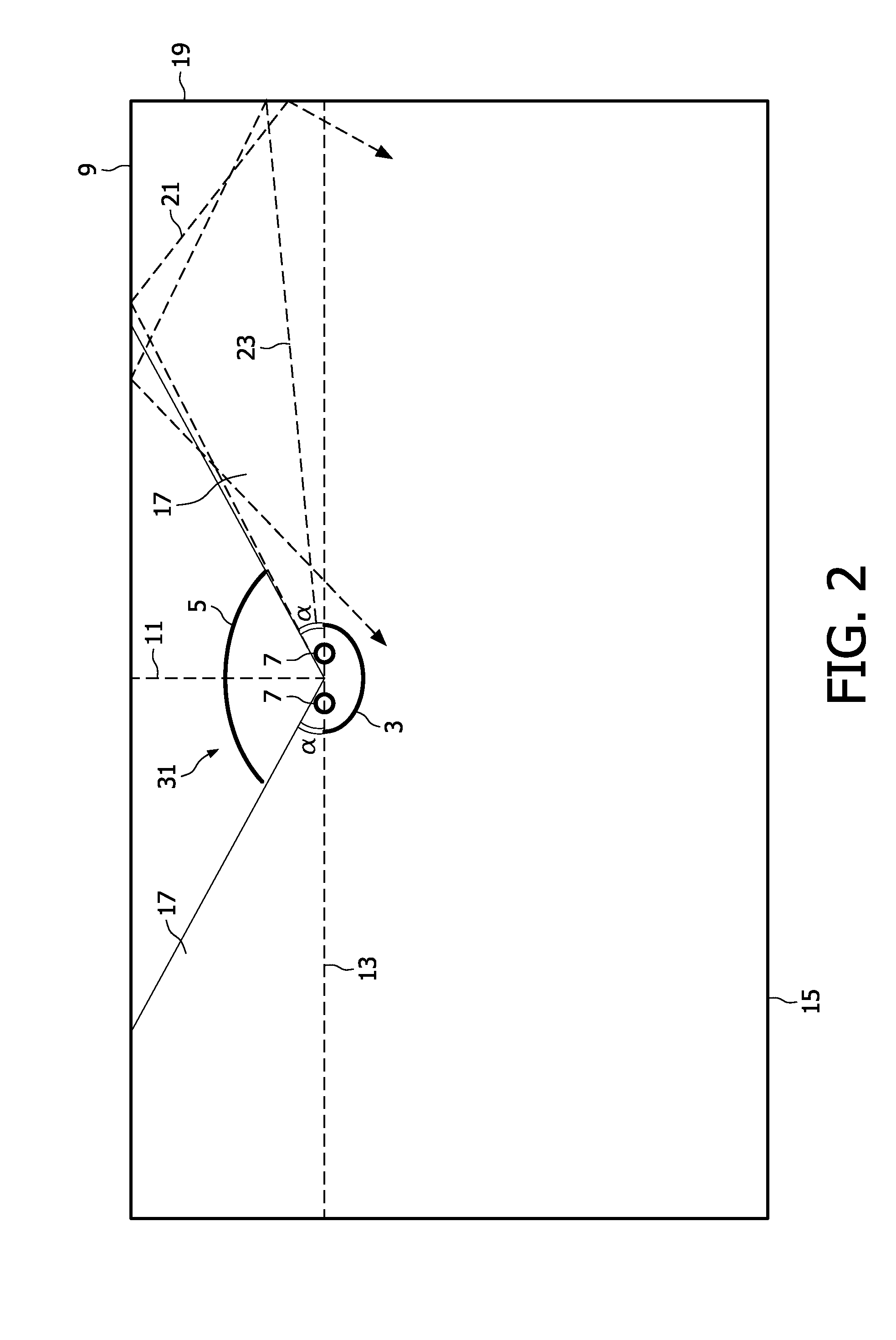
[0028]Referring to FIG. 1, a cross-sectional and schematic drawing of an embodiment of an air purification system 1 according to the invention is shown. The air purification system 1 comprises a lower screen 3, an upper screen 5 and a radiation source 7 for generating UV-C radiation, i.e. radiation in a wavelength range of 280 nm to 200 nm or less. In an alternative embodiment, the radiation source 7 is arranged for generating UV-B radiation, i.e. radiation in a wavelength range of 280-320 nm. In a further alternative embodiment, the radiation source 7 is arranged for generating both UV-B and UV-C radiation. The air purification system 1 is suspended from the ceiling 9 of a structure, for example a hospital room, conference room, or a class room, to name a few. The lower screen 3, upper screen 5 and radiation source 7 are coupled to each other in a way known to the person skilled in the art to form a robust device, and the upper screen 5 is movable with respect to the radiation 7 al...


PUM

PropertyMeasurementUnit
wavelength rangeaaaaaaaaaa
reflection coefficientaaaaaaaaaa

Abstract

An air purification system for a structure includes a first radiation source for generating UV-B and / or UV-C radiation and having an imaginary horizontal plane intersecting with the center of the first radiation source. The system further includes a first screen facing the first radiation source for preventing UV radiation generated by the first radiation source from radiating directly outward from the air purification system into a space below the imaginary horizontal plane. A second screen, facing the first radiation source as well as the first screen, is adjustable with respect to the first radiation source and is at least partially coated with a photo-catalytic material at a surface facing the first radiation source.

Description

CROSS REFERENCE TO RELATED APPLICATIONS[0001]This application claims the benefit of European Application Number EP07114846, filed Aug. 23, 2007, which is incorporated herein in whole by reference.TECHNICAL FIELD[0002]The invention relates to an air purification system for a structure. The invention further related to a method for purifying air inside a structure using such a system.BACKGROUND[0003]Air disinfection systems using germicidal UV radiation, usually in the form of UV-C radiation, are known as such. The germicidal UV radiation disinfects the air by damaging DNA which will inactivate for example, viruses, bacteria, molds, and yeast that are present in the air. Such air disinfection systems are particularly used in places where relatively many people are present for a longer time, for example in office buildings, schools, waiting rooms in hospitals and in places where there is a high risk for infection by air transmittable diseases such as isolation rooms in hospitals, shelt...

Claims


Application Information

Patent Timeline
Patent Type & Authority Patents(United States)
IPC IPC(8): B03C3/00
CPCA61L9/205B01D53/007B01D53/885F21S8/04F21V33/00H01J61/35B01D2255/802B01D2259/802F21V7/0008F21Y2113/00F21Y2113/02F21Y2113/20
Inventor LEROUX, ALAIN LOUIS CLAUDEGEBOERS, JACQUES MARIA JOZEF
Owner KONINKLIJKE PHILIPS ELECTRONICS NV
Why Eureka
Try Eureka