Medical catheter and system for inserting a catheter into a vessel

a technology catheters, which is applied in the field of medical catheters and systems for insertion of catheters into vessels, can solve the problems of poor visibility of stents in x-ray images, limited ultrasound image resolution, and inability to assess deposits such as thickness or inflammatory processes, and achieves the effect of minimal stress and good assessment of the vessel wall

Active Publication Date: 2012-02-28
SIEMENS HEALTHCARE GMBH
View PDF30 Cites 36 Cited by
  • Summary
  • Abstract
  • Description
  • Claims
  • Application Information

AI Technical Summary

Benefits of technology

[0012]The object of the invention is therefore to find a medical system for introducing a catheter into a vessel, that with minimum stress to the patient enables a sound diagnosis of a stenosis, thus permitting a good assessment of the vessel wall and at the same time dilatation of the stenosis and positioning of a stent.

Problems solved by technology

The disadvantage of this method is that only the diameter of the vessel that can be used by the blood flow, i.e. the narrow part, is shown as a silhouette.
An assessment regarding deposits, such as thickness or inflammatory processes, is therefore not possible.
The disadvantage of this method is in the relatively poor visibility of the stent in the x-ray image.
The disadvantage of this method is in the limited resolution of the ultrasound images and that an additional catheter has to be inserted into the coronary vessels.
The disadvantage described above should be avoided with a combination catheter as described in international patent application WO 02 / 07601, but these images suffer from the relatively poor resolution of the ultrasound method.
Various clinical studies failed to determine an improved diagnostic method compared with angiography that would justify the higher price for this solution.
The displayed depth area of the vessels is somewhat limited with these solutions.
The stressful insertion of a new catheter is necessary to introduce a stent and again there is some uncertainty in the positioning of the stent.

Method used


Image

  • Medical catheter and system for inserting a catheter into a vessel
  • Medical catheter and system for inserting a catheter into a vessel
  • Medical catheter and system for inserting a catheter into a vessel

Examples


Embodiment Construction

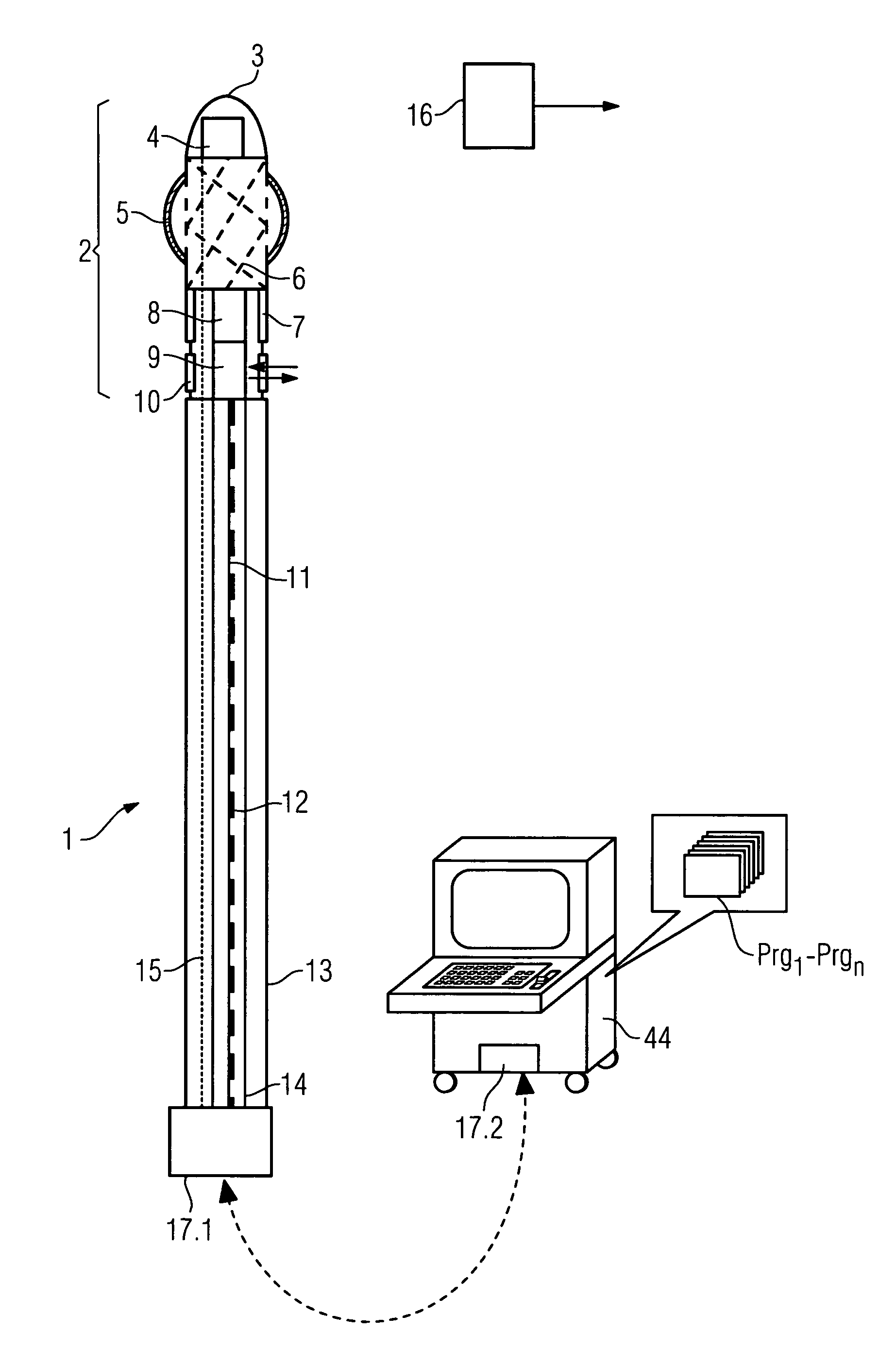
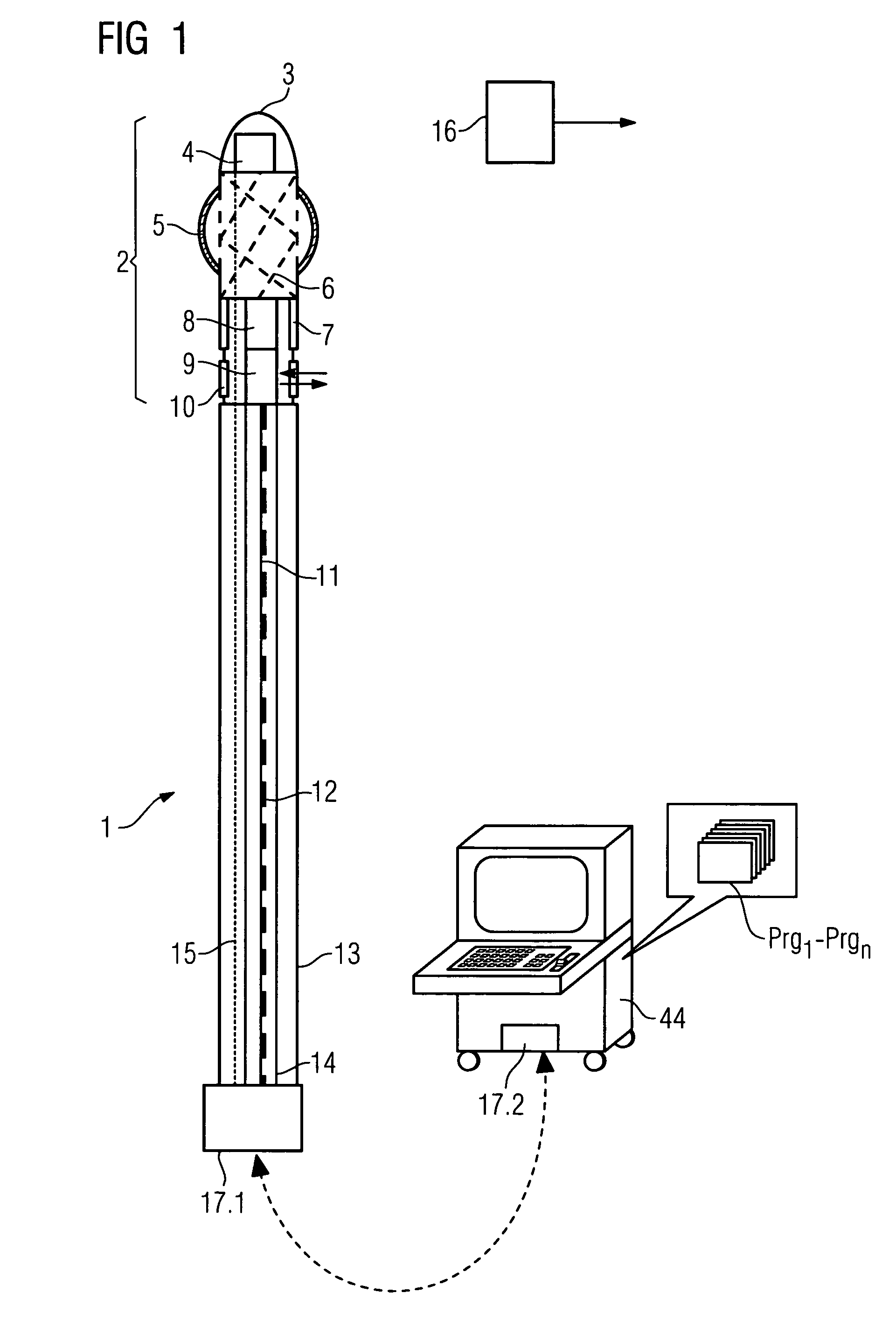
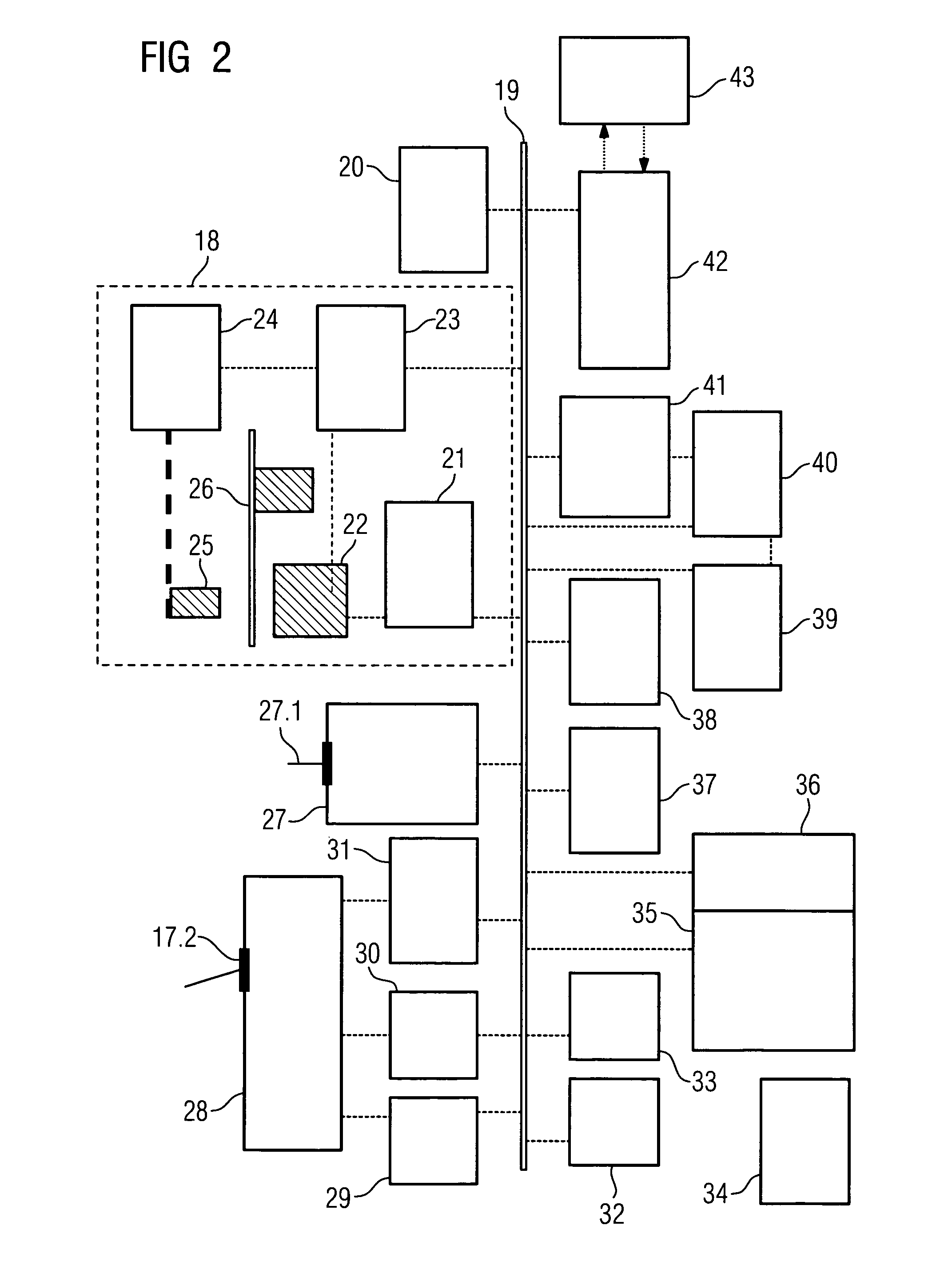
[0060]FIG. 1 shows a catheter in accordance with the invention with combined OCT / IVUS and EMP sensors and a stent with a dilatation balloon, whereas FIG. 2 shows a schematic general view of the periphery of this catheter. Both together correspond to the medical system in accordance with the invention, with the necessary and optional program means being shown only as functional units.

[0061]FIG. 1 shows the catheter 1 as a schematic longitudinal section. The catheter 1 consists, starting from the front, of a rounded catheter tip 3 behind which is arranged the magnetic sensors 4 for determining the position of the catheter. This is followed by an inflatable balloon 5 that can be inflated at the required point of the vessel by liquid or gas through a supply line. The fluid supply line to this balloon, which of course is present, is omitted for reasons of clarity. It is, however, pointed out that the balloon 5 can also be inflated by other means, for example by a mechanical spreader, wit...


PUM


Abstract

The invention relates to a medical system for introducing a catheter into a blood vessel of a patient, having a computer and control unit, a means for creating a transparent general view of the position of the vessel, a catheter with a reversible inflatable balloon located in the front area, to the outside of which a stent can be fitted for implanting into the vessel, a position locating system for the catheter with position and location sensors that can determine the position and location of the catheter, the system with at least one OCT (optical coherence tomography) sensor at a catheter end for the close-up area, with at least one IVUS (intravascular ultrasound) imaging sensor at a catheter end for the remote area and the computer and control unit having image processing and image display functions for the image sensors.

Description

CROSS REFERENCE TO RELATED APPLICATIONS[0001]This application claims the benefits of German Patent application No. 10 2005 027 951.1 filed Jun. 16, 2005 and is incorporated by reference herein in its entirety.FIELD OF THE INVENTION[0002]The invention relates to a medical system for the insertion of a catheter into a vessel, preferably a blood vessel of a patient, with a computer and control unit, a means for creating a transparent general image of the position of the vessel, a catheter, located in the front area, with a reversible inflatable balloon on the outside of which a stent can be arranged for implanting in a vessel, and a locating system for the catheter with position and location sensors that can determine the position and location of the front area of the catheter in the space by position sensors (EMP) fitted thereto.BACKGROUND OF THE INVENTION[0003]One of the most common causes of death in the world is vascular illnesses, particularly cardiac infarction. This is caused by...

Claims


Application Information

Patent Timeline
Patent Type & Authority Patents(United States)
IPC IPC(8): A61B5/00A61F2/958
CPCA61B1/042A61B1/313A61B6/12A61B8/12A61B19/52A61M25/01A61B5/0035A61B8/4472A61B8/445A61M25/104A61B6/5247A61B5/7285A61B5/062A61B2019/5251A61B5/0066A61B90/36A61B2034/2051A61B2562/17
Inventor MASCHKE, MICHAEL
Owner SIEMENS HEALTHCARE GMBH
Why Eureka
Try Eureka