
Image processing method, image processing apparatus, image forming system and recording medium readable by a computer

a technology of image processing and computer, applied in the direction of digital computers, visual presentations, instruments, etc., can solve the problems of image degradation, small text, small symbol or the like in a reduced image becoming unreadable, and causing image degradation, so as to prevent image degradation, reduce text, graphic or the like, and avoid noticeable graininess.

Active Publication Date: 2012-03-06
SHARP KK
View PDF15 Cites 8 Cited by
  • Summary
  • Abstract
  • Description
  • Claims
  • Application Information

AI Technical Summary

Benefits of technology

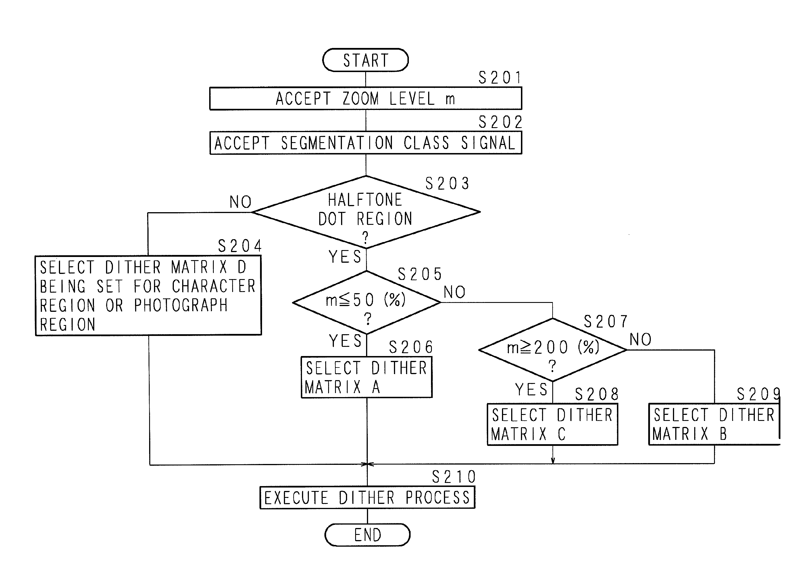
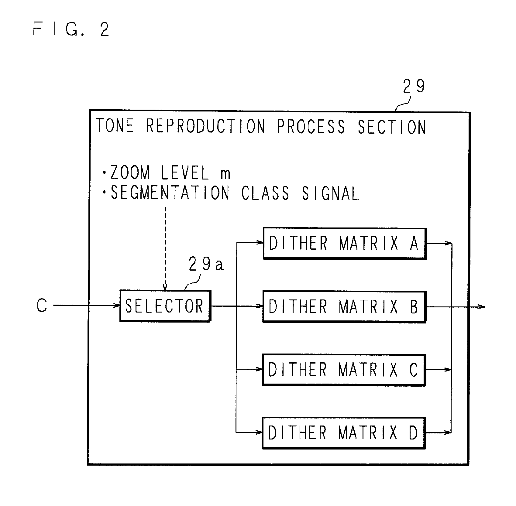
The present invention provides an image processing method that can change the magnification of image data without causing graininess or interference patterns. The method uses different dither matrices with different resolutions for zoom processes and dithering processes, which helps to select the most suitable dither matrix for the image data. This results in a higher resolution for reduced image data and better reproduction of small text or graphics. The method can also detect halftone dot areas and select the appropriate dither matrix accordingly. Overall, the method improves image quality and prevents degradation of image data.

Problems solved by technology

H1-136465 has a problem such as graininess deterioration or generation of an interference pattern which causes image degradation, since a zoom process is performed for a pixel of an image binarized in a tone reproduction process, that is, a binarized pixel which is white or black is interpolated or downsampled.
Accordingly, there is a problem that a small text, a small symbol or the like in a reduced image becomes unreadable because of insufficient resolution when a tone reproduction process is executed for an image data after zoom process to reduce an output size of the image.
Furthermore, when a tone reproduction process is executed for an image data after zoom process to enlarge an output size of the image, there is a problem that image degradation is caused because graininess is further emphasized by enlargement of the image.

Method used


Image

  • Image processing method, image processing apparatus, image forming system and recording medium readable by a computer
  • Image processing method, image processing apparatus, image forming system and recording medium readable by a computer
  • Image processing method, image processing apparatus, image forming system and recording medium readable by a computer

Examples


embodiment 1

(Embodiment 1)

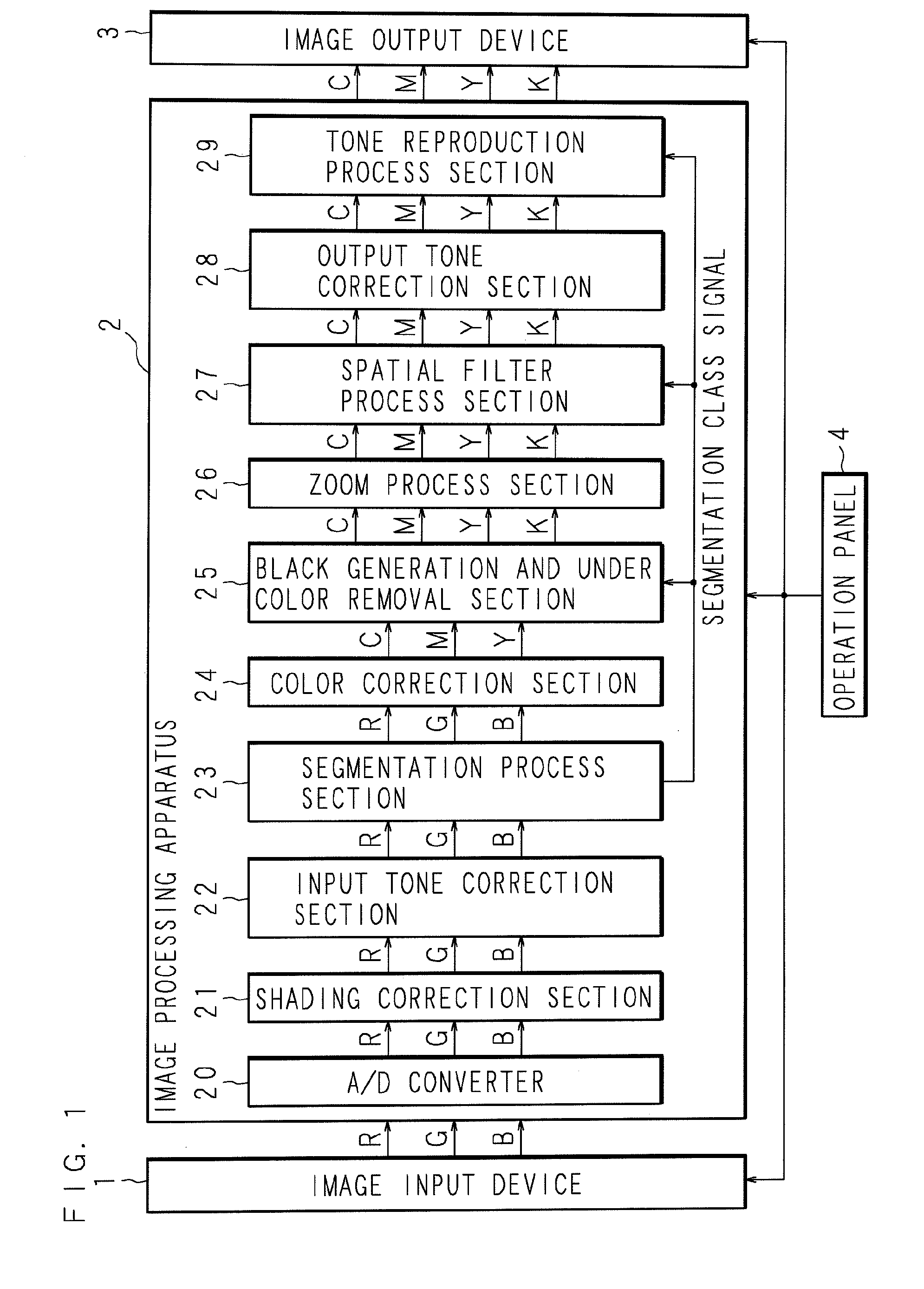
[0036]The following description will explain an image processing method, an image processing device, an image forming system, a computer program and a computer program product according to the present invention with reference to the drawings illustrating some embodiments thereof. FIG. 1 is a block diagram for showing an entire structure of an image forming system including an image processing apparatus according to Embodiment 1. The description of Embodiment 1 will explain an example in which an image forming system is a digital color copying machine. However, an image forming system according to the present invention is not limited to this and may be a digital color copying machine, a digital color complex machine or the like. Moreover, the present invention can be also applied to a case in which an image read by an image reading apparatus such as a scanner is outputted by a printer such as a color printer.

[0037]The image forming system in FIG. 1 is composed of an ima...

embodiment 2

(Embodiment 2)

[0090]The description of Embodiment 1 explains an example of selection of a dither matrix having a predetermined LPI depending on a zoom level or selection of a dither matrix having an LPI based on a zoom level regarding a region that is judged to be a halftone dot region by the segmentation process section 23. However, the present invention is not limited to this. A dither matrix having a predetermined LPI may be selected depending on the document type. In view of this fact, the description of Embodiment 2 will explain an example in which the image processing apparatus 2 is provided with a function for discriminating the document type of inputted image data. It should be noted that the description of Embodiment 2 explains an example in which the image forming system is a digital color complex machine. FIG. 9 is a block diagram for showing the entire structure of an image forming system comprising an image processing apparatus according to Embodiment 2.

[0091]The image ...

embodiment 3

(Embodiment 3)

[0127]The above description of Embodiments 1 and 2 explains an example in which the image processing apparatus 2 in the image forming system executes the document type discrimination process, the zoom process, the segmentation process, the matrix selection process and the halftone process. However, the present invention is not limited to this. An image reading apparatus may execute only the document type discrimination process, the zoom process and the segmentation process. The image reading apparatus is, for example, a flatbed scanner. FIG. 13 is a block diagram for showing the entire structure of an image reading apparatus according to Embodiment 3.

[0128]The image reading apparatus in the figure is composed of an image input device 5 and an image processing apparatus 6. The image input device 5 is, for example, a scanner provided with a CCD (Charged Coupled Device), which accepts reflected light from a document as an RGB analog signal and outputs the signal to the im...


PUM


Abstract

The image processing apparatus executes a zoom process to an image data depending on a received zoom level, selects a dither matrix from a plurality of dither matrices each having a different resolution. The image processing apparatus selects a dither matrix that has a higher resolution in a case that the received zoom level is equal or less than a first zoom level to reduce the image data. Furthermore, the image processing apparatus selects a dither matrix that has a lower resolution in a case that the received zoom level is equal or more than a second zoom level to enlarge the image data.

Description

[0001]This Nonprovisional application claims priority under 35 U.S.C. §119(a) on Patent Application No. 2007-268171 filed in Japan on Oct. 15, 2007, the entire contents of which are hereby incorporated by reference.BACKGROUND OF THE INVENTION[0002]1. Field of the Invention[0003]The present invention relates to: an image processing method which enables a zoom process of enlargement or reduction for image data as well as a dither process for producing halftone; an image processing apparatus for executing the method; an image forming system provided with the apparatus; and a recording medium which records a computer program for causing a computer to execute the method.[0004]2. Description of Related Art[0005]Conventionally, an image forming system for carrying out digital processing to a color image and outputting the image, such as an electrophotographic digital color multi function peripheral, an inkjet color printer or a thermal transfer color printer, is increasingly popular in the...

Claims


Application Information

Patent Timeline
Patent Type & Authority Patents(United States)
IPC IPC(8): H04N1/405
CPCH04N1/3935H04N1/405
Inventor GOTOH, MAKIO
Owner SHARP KK
Learn More