
Method for preprocessing vibro-sensor signals for engine diagnostics and device for carrying out thereof

a technology of vibrosensor and engine, which is applied in the direction of volume measurement apparatus/methods, complex mathematical operations, liquid/fluent solid measurement, etc., can solve the problem of increasing the stochastic component of the signal, and achieve the effect of reducing diagnostic costs, simple measurement techniques, and more precis

Inactive Publication Date: 2012-03-06
KIRILLOV SERGEY +2
View PDF7 Cites 3 Cited by
  • Summary
  • Abstract
  • Description
  • Claims
  • Application Information

AI Technical Summary

Benefits of technology

"The present invention provides a new method for analyzing signals from an internal combustion engine to improve diagnosis and prediction of failures. The method takes into account the non-stationary nature of the signal, the quasi-periodical character of the signal, and the stochastic combustion sub-component. The method uses a general sampling approach to create a reduced length cycle through the creation of a variable that depends upon the engine's crankshaft rotation angle. The method also includes dividing the signals into idling cycles, determining the crankshaft position, and using discrete and continuous wavelet transforms to obtain output data. The technical effects of the invention include improved accuracy and precision of engine diagnosis, reduced diagnostic costs, and simplified measurement techniques."

Problems solved by technology

This leads to an increase of a stochastic component of the signal, since the combustion is a turbulent process that involves complicated stochastic factors.
The classical vibration diagnostics are based on a simply understood notion adopted by those skilled in the art with application of ‘standard’ mathematical approaches, not requiring high computing resources, whereas the physical nature of the stochastic sub-components cannot be described by the ‘standard’ set of parameters contemplated by the classical diagnostics, which, in turn, causes a problem.

Method used


Image

  • Method for preprocessing vibro-sensor signals for engine diagnostics and device for carrying out thereof
  • Method for preprocessing vibro-sensor signals for engine diagnostics and device for carrying out thereof
  • Method for preprocessing vibro-sensor signals for engine diagnostics and device for carrying out thereof

Examples


Embodiment Construction

[0024]While the invention may be susceptible to embodiment in different forms, there are shown in the drawing, and will be described in detail herein, specific embodiments of the present invention, with the understanding that the present disclosure is to be considered an exemplification of the principles of the invention, and is not intended to limit the invention to that as illustrated and described herein.

PPD Structure

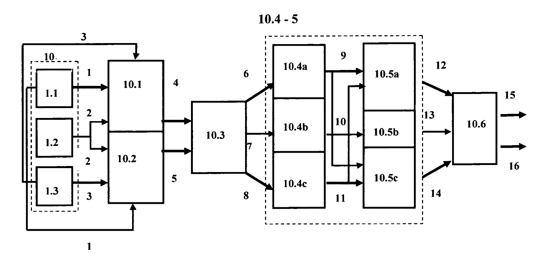
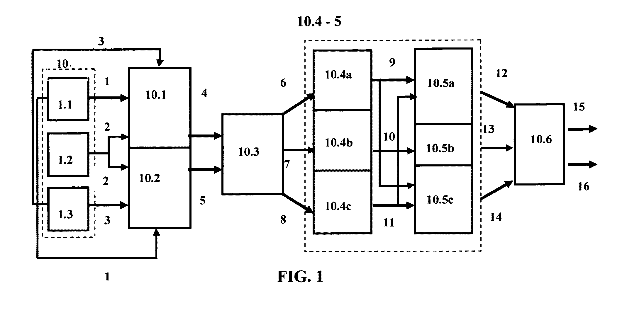
[0025]A generalized block-diagram particularly showing a flow of signals within units of the inventive device (herein also called a ‘preprocessing device’ or ‘PPD’) is illustrated on FIG. 1. The PPD is used for diagnostics of an internal combustion engine (10) (shown on FIG. 1 by a dashed box), which engine generally including: at least two conventional cylinders (not shown); a conventional crankshaft (not shown); a conventional crankshaft rotation angle sensor (1.1), herein also called ‘CRAS’, capable of measuring rotation angles of the crankshaft, the CRAS possesse...


PUM


Abstract

A method is provided for improved diagnostics of an internal combustion engine that includes cylinders, a crankshaft, crankshaft rotation angle sensor (CRAS), a vibro-sensor, a logic-mark sensor, each sensor produces respective signals. The method contemplates receiving the signals dividing them into a plurality of idling cycles, determining the crankshaft's position based on stochastic filtration, quasicontinuous representation of the signal, the Kalman filter, a nonlinear stochastic filter, based on CRAS characteristics and quasicontinuous representation, determining the Riesz generator basis function based on technical characteristics of the vibro-sensor, secondary discreeting of the signals with a replacement of argument, discreeting of a reciprocal function, obtaining a discrete wavelet transform, obtaining a continuous wavelet transform, obtaining a discrete wavelet transform of a reciprocal function, and producing output data. Two-dimensional arrays are divided relatively to predetermined indexes in the discrete transforms, an empirical probability distribution function is computed. Further optional diagnostic processing is provided.

Description

FIELD OF THE INVENTION[0001]The invention relates to systems and methods providing diagnostics and monitoring internal combustion engines, specifically to systems and methods for diagnostics of the engines based on analysis of at least engine vibrations.BACKGROUND OF THE INVENTION[0002]There exists a wide variety of diagnostic systems for combustion engines generally designed to detect present and future failures of such engines. Exemplarily, U.S. Pat. No. 7,403,850 to Boutin et al teaches an “automated fault diagnostic system” that “operates on engine-compressor sets with one vibration sensor per sub-group of engine cylinders and one sensor per compressor cylinder. Vibration signals linked to crankshaft phase angle windows (“VT”) mark various engine events and compressor events. In data-acquisition-learning mode, VT is stored for each engine and compressor event per operating load condition, statistical process control (SPC) theory identifies alarm threshold bands. Operator input-o...

Claims


Application Information

Patent Timeline
Patent Type & Authority Patents(United States)
IPC IPC(8): G01F23/00G06F19/00
CPCG01M15/12
Inventor KIRILLOV, SERGEYKIRILLOV, ALEKSANDRLASKIN, NIKOLAI
Owner KIRILLOV SERGEY
Learn More