Unlock instant, AI-driven research and patent intelligence for your innovation.

ILP rail-gun armature and rails

a technology of rail gun and armature, applied in the direction of weapons, launching weapons, white arms/cold weapons, etc., can solve the problems of arcing and heating between the armature and the rail, affecting the development of the rail gun, and affecting the effect of metal fusion

Active Publication Date: 2012-03-13
TEXAS RES INT
View PDF31 Cites 3 Cited by
  • Summary
  • Abstract
  • Description
  • Claims
  • Application Information

AI Technical Summary

Benefits of technology

[0020]A rail gun armature assembly utilizing unique carbon-carbon composite materials and armature design to enable repeated use of very high velocity projectile firings with minimal damage to rail guns meets this need. In addition a rail gun rail utilizing unique carbon-carbon composite materials to enable repeated use of very high velocity projectile firings with greatly reduced damage to the gun rails meets this need.

Problems solved by technology

A disadvantage of the conventional rail-gun is that arcing and heating may occur between the armature and rails.
The heating is due to I2R losses and the arcing is due to poor contact between the armature and rails.
Maintaining good electrical contact between the armature and the rails over the entire length of the rails without causing too much friction is a serious problem that has impeded rail gun development to date.
If the contact between the armature and rails is too tight, friction slows the armature, metal fusion occurs, and degrades projectile velocity.
If the contact between the armature and rails is too loose, arcing occurs.
Significant damage to the rails can occur due to the friction of the armature, metal fusion, and arcing.
Damage to the rails results in limited life for the EMRG rails necessitating replacement of the rails.
However, it was soon found that at high speeds around one kilometer per second, the rails and armature were substantially damaged, possibly as a result of ohmic heating and / or internal forces.
Further, increases in current flow tended to increase rail and armature gouging.
Current rail gun armature materials are less than optimal because the conditions encountered during launch deteriorate the armatures, which leads to degradation of the rails.
Thermal stresses, caused by loss of armature / rail contact, typically dominate armature deterioration.
Because of this local reversal, the magnetic force field is no longer able to counteract the blow-off force generated by the current through the armature-rail contact.
With the elevated temperature, the aluminum's mechanical properties are no longer sufficient to prevent the legs of the armature from moving away from the rail.
This loss of contact resulting in increased arcing and further melting of the armature material.
Rail damage comes in many forms.
Some damage is caused at start up, such as rail damage in the form of axial grooves.
At 1.4-1.7 MA, a single shot evidences this damage, but after 20 shots at 1.5 MA, the life of copper rails becomes limited.
The most troublesome damage is incurred during the transition from metal to metal contact to plasma contact during firing, which causes significant melting of the aluminum.
The melted aluminum adversely reacts with the copper rails, forming aluminide and creating pitting and gouging in the rails.

Method used


Image

  • ILP rail-gun armature and rails
  • ILP rail-gun armature and rails
  • ILP rail-gun armature and rails

Examples


Embodiment Construction

[0025]In the following detailed description, reference is made to the accompanying drawings that illustrate embodiments of the present invention. These embodiments are described in sufficient detail to enable a person of ordinary skill in the art to practice the invention without undue experimentation. It should be understood, however, that the embodiments and examples described herein are given by way of illustration only, and not by way of limitation. Various substitutions, modifications, additions, and rearrangements may be made without departing from the spirit of the present invention. Therefore, the description that follows is not to be taken in a limited sense, and the scope of the present invention is defined only by the appended claims.

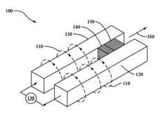
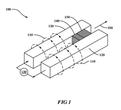
[0026]An electromagnetic rail gun 100 is shown isometrically in FIG. 1. Two rails 120 are on either side of a central core in which an armature 140 rides behind, or in some cases slightly surrounds, a projectile 150. A large electric current ...


PUM


Abstract

A rail gun armature assembly utilizing unique carbon-carbon composite materials and armature design to enable repeated use of very high velocity projectile firings with minimal damage to rail guns, and a rail gun rail assembly utilizing unique carbon-carbon composite materials to enable repeated use of very high velocity projectile firings with greatly reduced damage to the gun rails.

Description

BACKGROUND OF THE INVENTION[0001]1. Field of the Invention[0002]The present application is directed to electromagnetic rail-guns and, more particularly, to projectiles launched from electromagnetic rail-guns and the conducting rails used in the rail-gun system.[0003]2. Description of Related Art[0004]Electromagnetic rail-guns utilize an electromagnetic force called the Lorentz force to propel an electrically conductive integrated launch package (ILP). In a typical electromagnetic rail-gun, the ILP slides between two parallel rails and acts as a sliding switch or electrical short between the rails. By passing a large electrical current down one rail, through the ILP, and back along the other rail, a large magnetic field is built up behind the ILP, accelerating it to a high velocity by the force of the current times the magnetic field. An electromagnetic rail-gun is capable of launching an ILP to velocities greater than fielded powder guns, thereby achieving greater ranges and shorter...

Claims


Application Information

Patent Timeline
IPC IPC(8): F41B6/00
CPCF41B6/006
Inventor PERKINSON, JR., HARRY EBIFF
Owner TEXAS RES INT