Methods and systems for reducing interrupt latency by using a dedicated bit

Active Publication Date: 2012-03-13
TAHOE RES LTD
View PDF22 Cites 15 Cited by
  • Summary
  • Abstract
  • Description
  • Claims
  • Application Information

AI Technical Summary

Benefits of technology

[0004]In one aspect, a system for reducing interrupt latency is described. The system includes a first interrupt source configured to generate a first interrupt, a second interrupt source configured to generate a second interrupt, and a processor. The processor includes a register file, which further includes a normal set and one or more shadow sets. The shadow set stores data used to service the first interrupt. The processor receives the second interrupt and receives a designation of the shadow set to service the second interrupt. The processor determines, based on a dedicated bit, whether the shadow set is used to service the first interrupt upon receiving the second interrupt.
[0005]Processor also includes an SSTATUS register including a switched register set (SRS) field and a comparator. The dedicated bit is the SRS field of the SSTATUS register. The dedicated bit is set to 1 by the comparator upon determining that the shadow set is not in use preceding to a use for an external interrupt and the dedicated bit is set to 0 by the comparator upon determining that the shadow set is in use preceding to the use for the external interrupt. The dedicated bit is set to 1 by the comparator if taking the external interrupt causes the processor to switch to a shadow set that is not in use. By reading the SRS field in a single instruction cycle, the processor determines whether or not to save a portion of the shadow set. This reading of the SRS field reduces interrupt latency because the additional overhead of reading the SRS field is minimal and saves a lengthy operation of saving context.

Problems solved by technology

This reading of the SRS field reduces interrupt latency because the additional overhead of reading the SRS field is minimal and saves a lengthy operation of saving context.

Method used


Image

  • Methods and systems for reducing interrupt latency by using a dedicated bit
  • Methods and systems for reducing interrupt latency by using a dedicated bit
  • Methods and systems for reducing interrupt latency by using a dedicated bit

Examples


Embodiment Construction

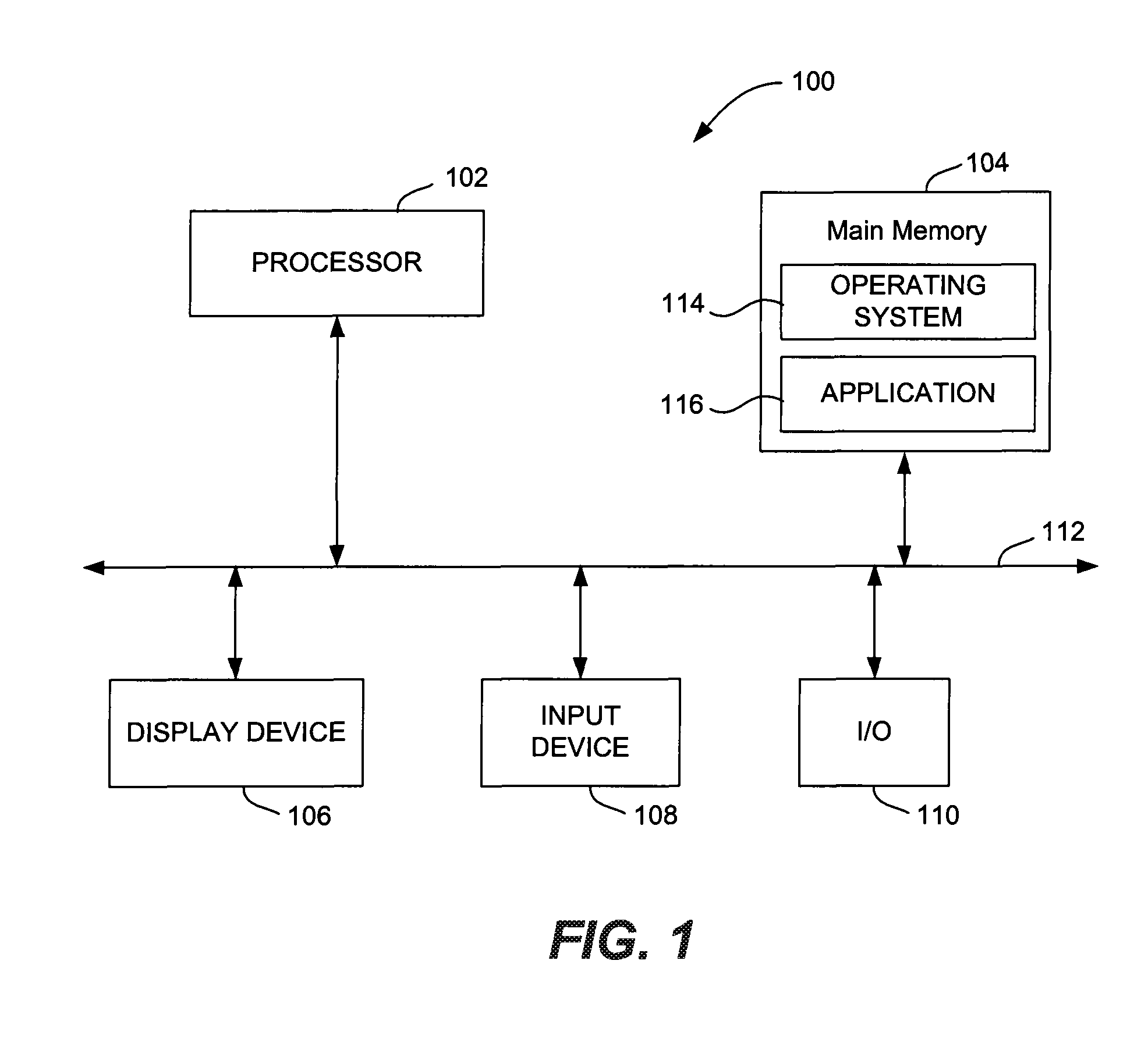
[0015]FIG. 1 is a block diagram of an embodiment of a system 100 for reducing interrupt latency. System 100 includes a processor 102, a main memory 104, a display device 106, and input device 108, and an input / output (I / O) interface 110. Processor 102, main memory 104, display device 106, input device 108, and I / O interface 110 are connected via a bus 112, which includes a data bus, a control bus, and an address bus. Input device 108 may be a touch screen, a keyboard, a mouse, or a stylus. Examples of display device 106 include a cathode ray tube (CRT), a liquid crystal display (LCD), a plasma display, or a light emitting diode (LED) display used to display information to a user. Processor 102 is a microprocessor, a central processing unit (CPU), or a part of a microcontroller. I / O interface 110 connects processor 102 to a peripheral device, such as a modem, a network interface card (NIC), a printer, or a scanner.

[0016]Main memory 104 includes a random access memory (RAM) or a combi...


PUM


Abstract

A system and a method for reducing interrupt latency is described. The system includes a first interrupt source configured to generate a first interrupt, a second interrupt source configured to generate a second interrupt, and a processor. The processor includes a shadow set that stores data used to service the first interrupt. The processor receives the second interrupt and receives a designation of the shadow set to service the second interrupt. The processor determines, based on a dedicated bit, whether the shadow set is used to service the first interrupt upon receiving the second interrupt.

Description

FIELD OF THE INVENTION[0001]The present disclosure generally relates to interrupt latency and more particularly to systems and methods for reducing interrupt latency.BACKGROUND[0002]Interrupt latency includes a number of clock cycles between an assertion of an interrupt by an interrupt source and execution of an initial non-prologue instruction in an interrupt service routine (ISR). The interrupt latency includes a cause latency, a selection latency, and a funnel latency. The cause latency is a number of cycles for a processor to determine that an interrupt is a reason to arrive at an address of an initial instruction of the ISR. The selection latency is a number of clock cycles for the processor to choose among multiple interrupts. The funnel latency includes a number of clock cycles in an interrupt funnel. The funnel latency includes a context overhead, a real-time operating system (RTOS) overhead, and a call overhead. The context overhead includes a number of clock cycles to save...

Claims


Application Information

Patent Timeline
IPC IPC(8): G06F13/26
CPCG06F13/26
Inventor BALL, JAMES L.
Owner TAHOE RES LTD
Why Eureka
Try Eureka