
Turbomachine shaft guidance

a technology of shaft guidance and turbine blades, which is applied in the direction of liquid fuel engines, vessel construction, marine propulsion, etc., can solve the problems of increased fan blades, significant imbalance, damage to turbine blade blades, etc., and achieves the effect of simple, economical and effectiv

Active Publication Date: 2012-03-20
SN DETUDE & DE CONSTR DE MOTEURS DAVIATION S N E C M A
View PDF7 Cites 25 Cited by
  • Summary
  • Abstract
  • Description
  • Claims
  • Application Information

AI Technical Summary

Benefits of technology

[0013]It is a particular object of the invention to provide a simple, economical and effective solution to these problems while at the same time avoiding the aforementioned disadvantages.
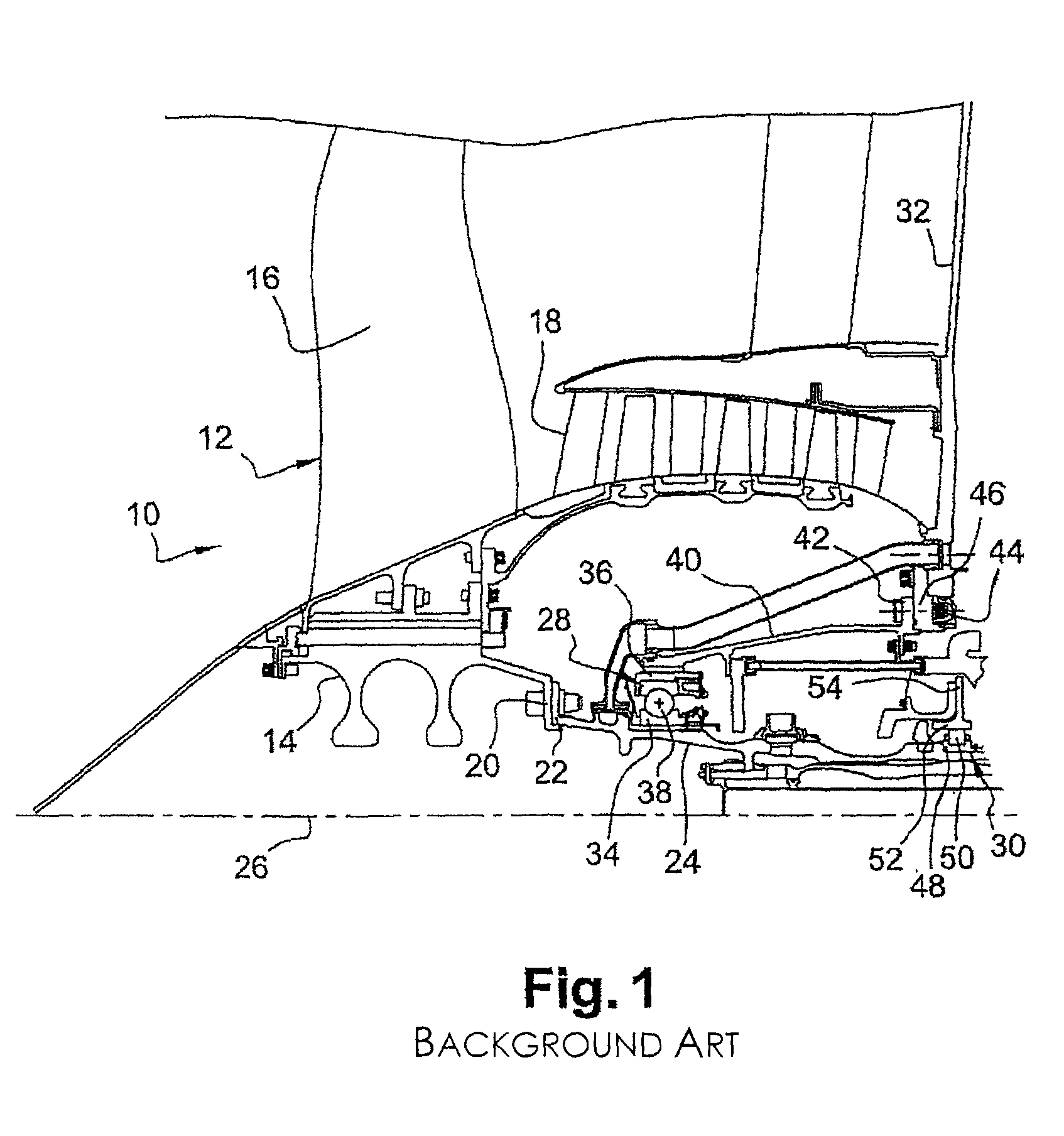
[0014]A particular object of the invention is to allow the low-pressure compressor shaft to be recentred once one of its guide bearings has been uncoupled, as soon as the turbojet engine has reached its autorotation speed so as to avoid the other guide bearing becoming destroyed and preserve the structure of the turbojet engine.
[0019]Further, the bearings are capable of ensuring axial retention of the upstream end of the shaft, even during uncoupling.
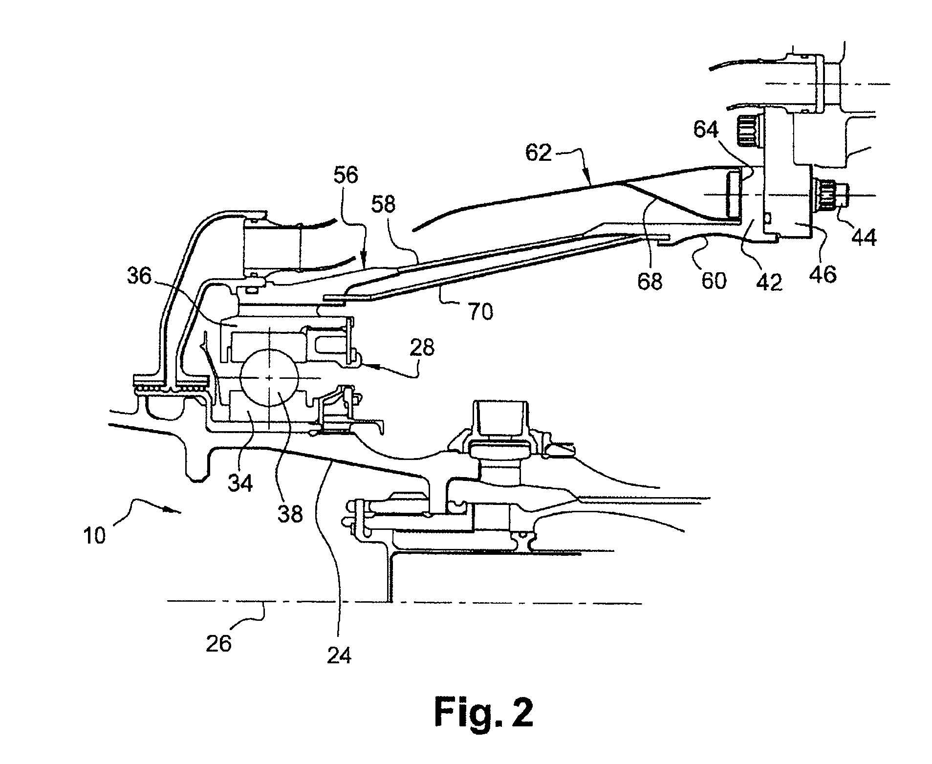
[0025]In the case of a material of the “single-acting” type, the sheet metal deflector allows better guidance of the hot air intended to trigger the transition of the shape memory material into the austenitic phase.
[0027]This means that the substantial ability of superelastic shape memory materials to deform can be put to good use in avoiding the need to resort to means of heating the annular part of the bearing support.
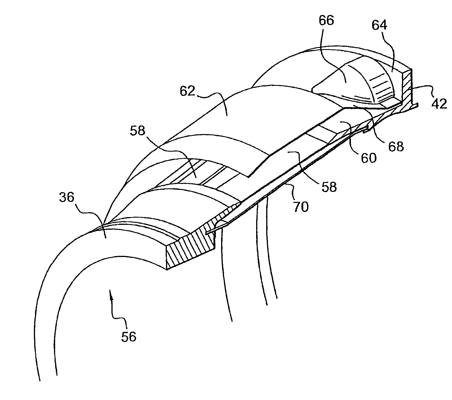
[0033]This annular sealing envelope is particularly useful in instances where the shape memory annular part comprises thin longitudinal blades of the type mentioned hereinabove, in order to seal the space between the bearings and thus prevent oil from leaking from that space.

Problems solved by technology

Turbojet engine fan blades may be subjected to damage, for example following ingestion of foreign objects such as birds or blocks of ice.
However, ingestion of a foreign body can sometimes cause one or more fan blades to break, this being liable to have the effect of causing significant imbalance requiring the engine to stop, and capable of subjecting the structure of the turbojet engine to considerable cyclic forces, at least while the engine is slowing down to its windmilling or autorotation speed, that is to say to its speed of free rotation as a result of its movement through the atmosphere.
However, when the upstream bearing has been decoupled from the stator it no longer centres the low-pressure compressor shaft and even though the loads resulting from the imbalance are not of such a great magnitude once the autorotation speed has been reached, these loads are then essentially borne by the downstream bearing, with a risk therefore of breaking the latter.
To avoid this disadvantage, devices have been proposed in which the downstream bearing is, for example, mounted on a support that is articulated to allow the shaft to become off-centred without destroying this downstream bearing, but these devices lead to additional mass penalizing turbojet engine performance.
Furthermore, with the known devices and should the low pressure compressor shaft break, the upstream part thereof is no longer axially retained by the upstream bearing, thus potentially endangering the turbojet engine.

Method used


Image

  • Turbomachine shaft guidance
  • Turbomachine shaft guidance
  • Turbomachine shaft guidance

Examples


first embodiment

[0055]In a first embodiment, the thin blades 58 are made of a shape memory material of the “single-acting” type, such as an alloy of nickel and of titanium, commonly known as Nitinol.

[0056]The shape memory material, which is initially in the martensitic phase, gives the thin blades 58 a good ability to deform and the possibility, when heated, of changing into the austenitic phase, reverting to a learned shape.

[0057]In order for the bearing support 56 to revert to its initial shape after having been deformed, the thin blades are prepared beforehand so that, in the austenitic phase, they adopt a shape similar to their initial shape prior to deformation, as will be explained in greater detail in a later paragraph dealing with the operation of the invention and more specifically with the use of “one-way” memory effect of the shape memory material, with reference to FIG. 4.

[0058]To heat the thin blades 58, the turbojet engine 10 comprises means for directing onto the thin blades air at a...

second embodiment

[0077]In a second embodiment, instead of using a one-way shape memory effect, the bearing support 56 according to the invention may work by virtue of a superelastic effect of the shape memory material of which the thin blades 58 are made.

[0078]In this embodiment, the shape memory material is chosen such that it is in the austenitic phase at turbojet engine normal operating temperatures.

[0079]The imbalance forces applied to the bearing support 56 cause the shape memory material to pass under stress into the martensitic phase in which this material has an enormous capacity for elastic deformation.

[0080]As soon as the applied loads disappear or reduce sufficiently, the material returns to the elastic domain of the austenite, reverting to its initial shape.

[0081]This embodiment of the invention has the advantage of not requiring any means of heating the shape memory material, and therefore proves to be simpler to implement than the previously described first embodiment.

[0082]However, wh...


PUM


Abstract

A support for a bearing that guides a shaft in a turbomachine is disclosed. The support includes an annular part made of a shape memory material which retains an initial shape when the load applied to it remains below a threshold value and which deforms, absorbing energy when the applied load becomes at least equal to the threshold value. The annular part is capable of reverting at least approximately to its initial shape when the applied load drops back below the threshold value.

Description

BACKGROUND OF THE INVENTION[0001]1. Field of the Invention[0002]The present invention relates to supports for bearings that guide rotor shafts in turbomachines such as aircraft bypass turbojet engines.[0003]2. Description of the Related Art[0004]Turbojet engine fan blades may be subjected to damage, for example following ingestion of foreign objects such as birds or blocks of ice.[0005]In general, the fan is robust enough to withstand the effects of such an ingestion and to continue to operate, possibly at a lower speed.[0006]However, ingestion of a foreign body can sometimes cause one or more fan blades to break, this being liable to have the effect of causing significant imbalance requiring the engine to stop, and capable of subjecting the structure of the turbojet engine to considerable cyclic forces, at least while the engine is slowing down to its windmilling or autorotation speed, that is to say to its speed of free rotation as a result of its movement through the atmosphere.[...

Claims


Application Information

Patent Timeline
Patent Type & Authority Patents(United States)
IPC IPC(8): F16C27/00F01D25/16
CPCF01D21/045F01D25/164F05D2300/505F16C19/06F16C27/04F16C2360/23
Inventor MONS, CLAUDE MARCELRABERIN, LAURENTRONGVAUX, JEAN-MARCROUSSELIN, STEPHANE
Owner SN DETUDE & DE CONSTR DE MOTEURS DAVIATION S N E C M A
Learn More