Propulsion cell for a device in an aquatic medium

Active Publication Date: 2012-03-20
DCN INC
View PDF13 Cites 5 Cited by
  • Summary
  • Abstract
  • Description
  • Claims
  • Application Information

AI Technical Summary

Benefits of technology

[0008]The object of the present invention is to overcome the disadvantages of traditional electrical cells or sources of el

Problems solved by technology

Under these conditions, the use of conventional electrical energy sources, such as lead accumulator batteries, cannot be accepted owing, on the one hand, to the electrical power required to ensure such a function and, on the other hand, to the inert mass necessary in order to use such conventional sources of electrical energy.
Ther

Method used


Image

  • Propulsion cell for a device in an aquatic medium
  • Propulsion cell for a device in an aquatic medium
  • Propulsion cell for a device in an aquatic medium

Examples


Embodiment Construction

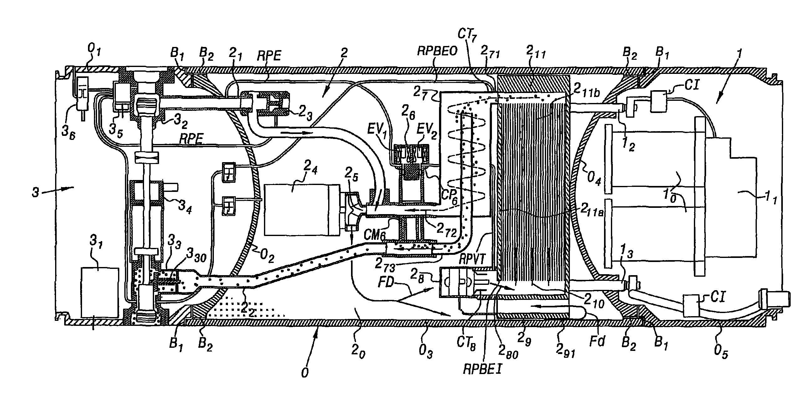
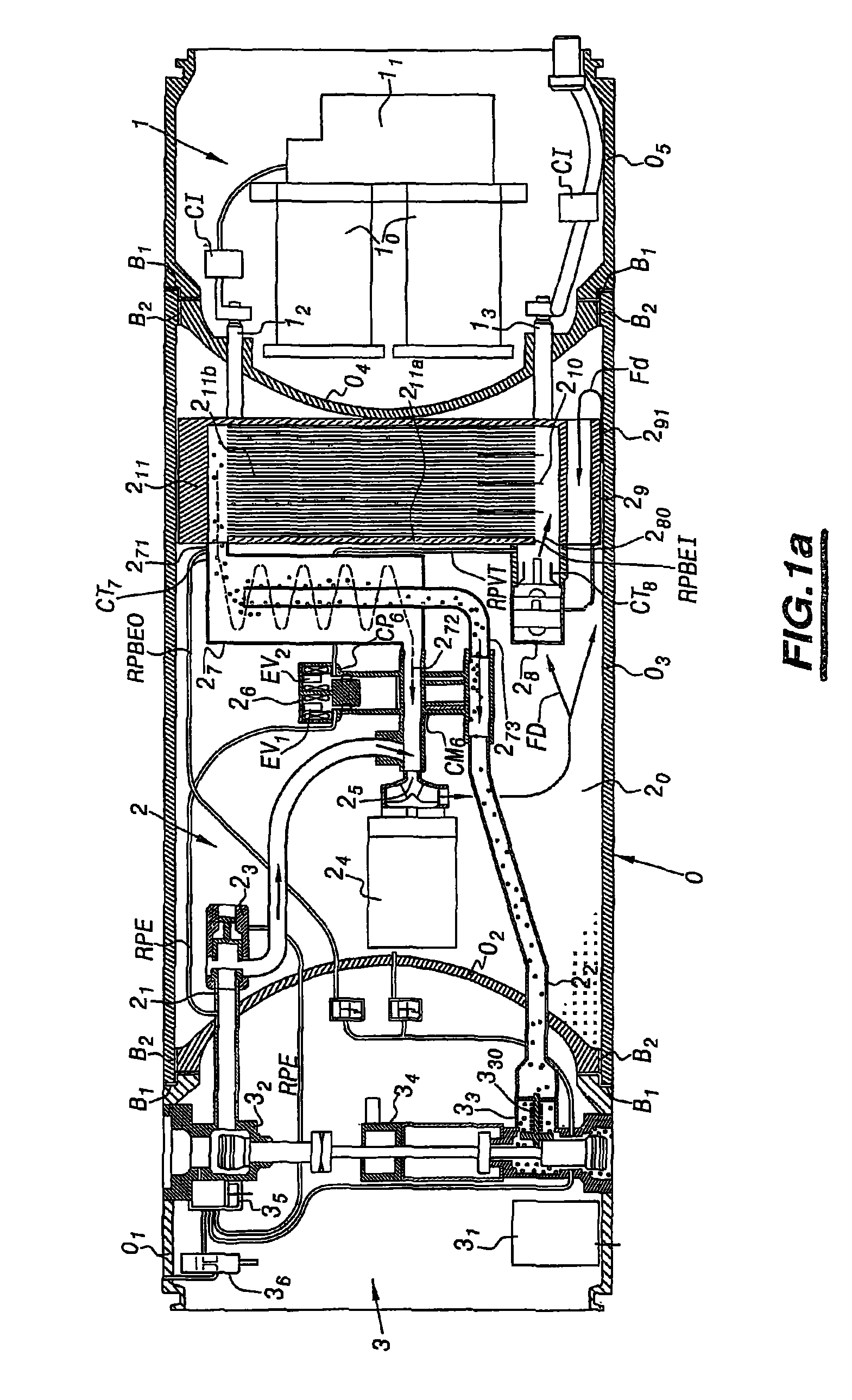
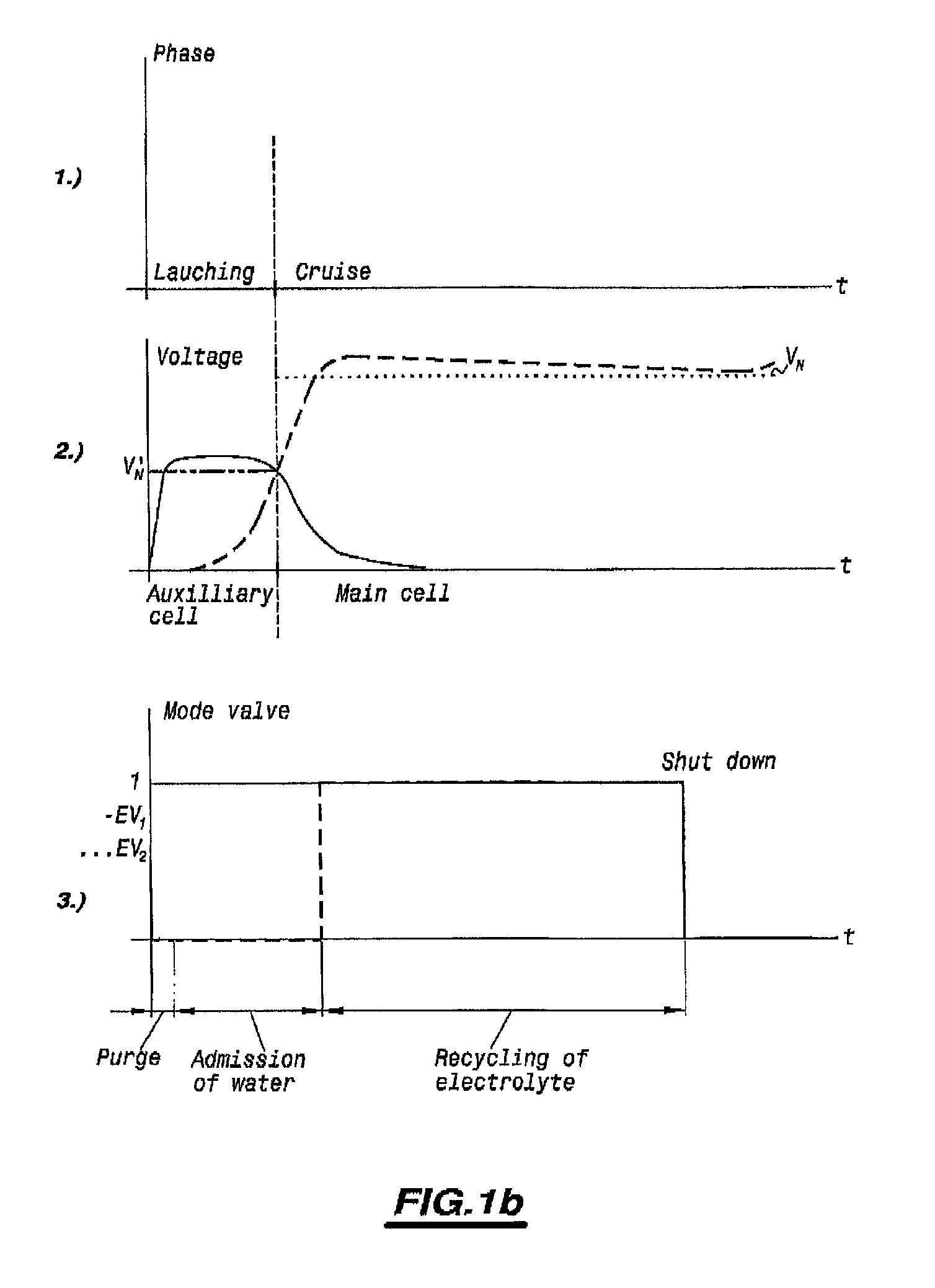
[0018]A more detailed description of the electrical cell for the propulsion of a device in an aquatic medium according to the subject-matter of the present invention will now be given in conjunction with FIG. 1a and then FIG. 1b.

[0019]As can be seen in the above-mentioned FIG. 1a, the electrical cell to which the invention relates comprises at least, in a sealed cell body marked 0, a first chamber 1, a second chamber 2 and a third chamber 3, each of the above-mentioned chambers forming a housing.

[0020]The first chamber 1 comprises an auxiliary electrical cell marked 10 and a command and control module marked 11 for the electrical propulsion cell.

[0021]The second chamber 2 comprises a main electrical cell marked 211, this main electrical cell advantageously being of the electrochemical type in order to operate under the conditions which will be explained hereinafter.

[0022]The second chamber 2 is also provided with members for the controlled admission and the regulation of a flow of ...


PUM


Abstract

An electrical cell for the propulsion of a device in an aquatic medium includes a first, second and third chamber forming a housing. The first chamber has an auxiliary electrical cell and a command and control module for the electrical propulsion cell, the second chamber a main electrical cell and members for the controlled admission and regulation of water flow from the aquatic medium in order to form an activation electrolyte for the main cell, and the third chamber a module for triggering the admission by suction of water and the discharge by escape of effluents from an admission valve and an escape valve. The command and control module activates the auxiliary electrical cell to generate electrical energy temporarily and the admission by suction of water from the aquatic medium and the discharge of effluents in order to produce electrical energy from the main electrical cell during a cruise phase.

Description

FIELD OF THE INVENTION[0001]The invention relates to an electrical cell for the propulsion of a device in an aquatic medium.BACKGROUND OF THE INVENTION[0002]The propulsion of devices in an aquatic medium, especially when these devices of the underwater type are moving, at least for a short while in the submerged state, requires the provision of a propulsive energy, such as electrical energy, under conditions of power, duration and modulation by successive ranges which are well determined.[0003]This is especially the case with underwater attack, response or observation devices launched from another carrying device, such as a submarine, such launched underwater devices then being subjected to a generally brief launch stage or phase followed by a longer cruise stage or phase.[0004]The supply of electrical energy to such launched underwater devices must then meet very specific criteria in respect of electrical power delivered and duration of delivery of this energy, in order to enable t...

Claims


Application Information

Patent Timeline
IPC IPC(8): H01M6/34B60L11/00B63H21/17B63G8/08F42B19/24F42B19/26H01M6/36H01M10/44H01M10/50H01M16/00H01M50/204H01M50/253H01M50/77
CPCF42B19/26H01M2/1077H01M16/00H01M6/36H01M10/441H01M10/501H01M10/5042H01M6/34B63G8/08B63G2008/004B63H21/17H01M10/654H01M10/62Y02E60/10H01M50/204H01M50/253
Inventor VIVIEN, DIDIERCARMILLET, JEAN-PIERRE
Owner DCN INC
Why Eureka
Try Eureka