Fuel cell system as a primary electrical energy supply for aircraft

a fuel cell and aircraft technology, applied in the direction of energy-efficient board measures, electrochemical generators, efficient propulsion technologies, etc., can solve the problems of low efficiency of cabin air conditioning systems, bleed air systems require considerable construction expenditure, and inability to operate with bleed air, so as to reduce in-flight fuel consumption, improve the efficiency of onboard energy generation, and reduce pollutant emissions

Active Publication Date: 2012-03-20
AIRBUS OPERATIONS GMBH
View PDF13 Cites 4 Cited by
  • Summary
  • Abstract
  • Description
  • Claims
  • Application Information

AI Technical Summary

Benefits of technology

[0008]By integrating fuel cells in the onboard energy supply system, it may for example possible to increase the efficiency of onboard energy generation and thus in the final analysis to reduce in-flight fuel consumption. The fuel cells may supply direct current directly, to high-voltage direct-current systems. The fuel cell system may have lower pollutant emissions than a comparable auxiliary power unit and may also generate considerably less noise.
[0009]Furthermore, in this way the maintenance expenditure relating to the main engines may be reduced, as may be the weight of the main engines. Due to the absence of any main engine generators both the efficiency and the by-pass ratio may be increased.
[0011]This may advantageously provide a possibility for individually regulating or controlling the energy, supply to the respective electrical consumers which are connected to the electrical energy supply device so that central energy management may be implemented.
[0013]In this way optimisation of the energy management may become possible such that high-priority consumers may in every case be supplied with sufficient electrical energy, while in the case of any supply bottleneck only less important consumers, i.e. consumers which are placed lower in the list of rankings, may receive an inadequate quantity of energy. Consequently, even in the case of a temporary shortfall in the supply of energy to the entire network, adequate energy supply to prioritised consumers may still be ensured.
[0015]In this way an onboard energy supply system may be advantageously stated which comprises an energy distribution device which can communicate with the corresponding regulating unit. For example, the signals transmitted can be in formation relating to the future energy requirements of a particular consumer. As a reaction to it, the regulating unit may for example further increase the output, or may reduce the output, of the at least one fuel cell module.
[0019]In this way the requirements relating to the statics of the primary structure of the aircraft may advantageously be reduced. Furthermore, by not having a device carrier the overall weight of the aircraft may be significantly reduced.

Problems solved by technology

Bleed air systems require considerable construction expenditure, e.g. for operating the pneumatic valves and intermediate cooling devices.
In such arrangements the maintenance effort on the engine and in the aircraft is considerable.
The efficiency of the cabin air conditioning systems, which are operated with bleed air, is low.
The hydraulic systems of the aircraft require considerable maintenance effort.
However, as a rule these additional generators cause the device carrier to be exposed to correspondingly heavy mechanical loads.
However, both concepts result in a heavy and inefficient engine that is difficult to regulate and furthermore is not easy to maintain.

Method used


Image

  • Fuel cell system as a primary electrical energy supply for aircraft
  • Fuel cell system as a primary electrical energy supply for aircraft
  • Fuel cell system as a primary electrical energy supply for aircraft

Examples


Embodiment Construction

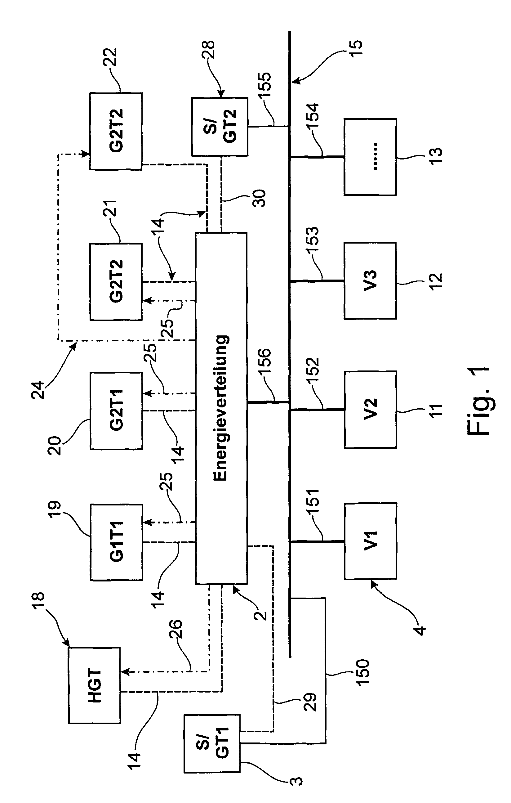
[0027]FIG. 1 shows a diagrammatic view of an electrical energy supply system for aircraft with generators which are driven by the engines. In this arrangement the energy supply substantially comprises an electrical onboard supply system 15, an energy distribution device 2 and electrical generators of the electrical generators 19 to 22 of the engine. In this arrangement the electrical generators 19 to 22 are driven by way of the engine and generate electrical energy which they supply to the energy distribution device 2 by way of the supply lines 14. The engine generators 19 and 20 are the first and the second engine generator of the first engine. The engine generators 21, 22 are the first and the second generator of the second engine (the engines are not shown in FIG. 1). Furthermore, an auxiliary power unit 18 is connected to the energy distribution device 2 by way of the supply line 14. The four engine generators 19 to 22 and the auxiliary power unit 18 are connected to the energy ...


PUM

PropertyMeasurementUnit
electrical energyaaaaaaaaaa
electricalaaaaaaaaaa
energyaaaaaaaaaa

Abstract

Apart from electrical energy, nowadays the main engines also supply pneumatic and hydraulic energy to the aircraft, using corresponding media. Apart from mechanical disadvantages this results in reduced engine efficiency in relation to thrust, fuel consumption and weight. According to an embodiment of the present invention an energy supply system for aircraft is provided, comprising a fuel cell arrangement and an electrical energy distribution device. In this way it is possible to replace all the energy generating systems of the engines, which provide energy for the aircraft systems, except for the starter generator, as a result of which the efficiency of the individual engines is improved. Furthermore, the efficiency of onboard energy generation is improved, which in the final analysis results in reduced fuel consumption.

Description

CROSS-REFERENCE TO RELATED APPLICATIONS[0001]This application claims the benefit of the filing date of U.S. Provisional Patent Application No. 60 / 609,968 filed Sep. 15, 2004, the disclosure of which is hereby incorporated herein by reference.BACKGROUND OF THE INVENTION[0002]In modern aircraft, various types of energy transmission are used for supplying aircraft systems. Apart from electrical energy, the main engines also supply pneumatic and hydraulic energy to the aircraft, using corresponding media. As a rule, the auxiliary power unit supplies pneumatic and electrical energy for starting the engines and for operating the aircraft both on the ground and in the event of an emergency.[0003]The hydraulic and the bleed air systems, which extend along large stretches through the aircraft, are associated with a host of disadvantages. Bleed air systems require considerable construction expenditure, e.g. for operating the pneumatic valves and intermediate cooling devices. In such arrangeme...

Claims


Application Information

Patent Timeline
Patent Type & Authority Patents(United States)
IPC IPC(8): H01M8/24H01M8/04B64D41/00
CPCB64D41/00H01M8/04992B64D2041/005B64D2221/00H01M8/0494H01M8/04955H01M8/249H01M2250/20H01M2250/402H01M2250/407Y02B90/12Y02T50/545Y02T90/36Y02E60/50Y02E60/563Y02T90/32Y02T50/54Y02B90/10Y02T50/50Y02T90/40
Inventor GANS, HUBERT
Owner AIRBUS OPERATIONS GMBH
Why Eureka
Try Eureka