Gas turbine combustion chamber made of CMC material and subdivided into sectors

a combustion chamber and cmc material technology, applied in the field of gas turbines, can solve the problems of complex shape of the combustion chamber walls, assembly cannot guarantee the constant axial position of the sectors, etc., and achieve the effects of reducing fabrication costs, reducing complexity of shapes, and reducing manufacturing costs

Active Publication Date: 2012-03-27
SN DETUDE & DE CONSTR DE MOTEURS DAVIATION S N E C M A
View PDF11 Cites 65 Cited by
  • Summary
  • Abstract
  • Description
  • Claims
  • Application Information

AI Technical Summary

Benefits of technology

[0010]Subdividing the combustion chamber into sectors enables the dimensions of the parts that are to be made to be limited and also limits the complexity of the shapes thereof, thereby significantly reducing the costs of fabrication, while incorporating the chamber end wall with the inner and outer walls. Furthermore, the differential variations in dimensions between the metal casings and the CMC combustion chamber walls can be absorbed easily and effectively by the elastic deformation of the link elements placed in the gaps between the inner and outer chamber walls and the metal casings, in which gaps they are immersed in the stream of air flowing around the combustion chamber. The link elements also contribute to holding the chamber sectors relative to one another, in particular in the axial direction.

Problems solved by technology

Making combustion chamber walls for a gas turbine requires tooling that is complex in shape.
Such an assembly does not guarantee that the sectors are maintained in a constant axial position, in particular when the applied stresses are high, as happens in the combustion chambers of aviation turbines.

Method used


Image

  • Gas turbine combustion chamber made of CMC material and subdivided into sectors
  • Gas turbine combustion chamber made of CMC material and subdivided into sectors
  • Gas turbine combustion chamber made of CMC material and subdivided into sectors

Examples


Embodiment Construction

[0026]Embodiments of the invention are described below in the context of its application to a gas turbine airplane engine. Nevertheless, the invention is also applicable to gas turbine combustion chambers for other aero-engines or for industrial turbines.

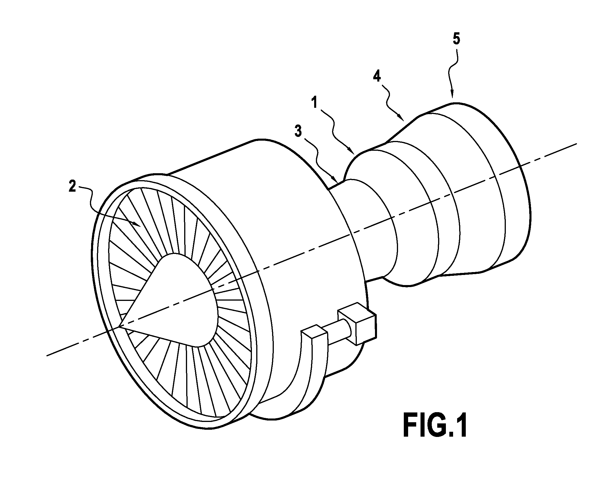
[0027]FIG. 1 is a highly diagrammatic view of a two-spool gas turbine airplane engine comprising, from upstream to downstream in the flow direction of the gas stream: a fan 2; a high pressure (HP) compressor 3; a combustion chamber 1; a high pressure (HP) turbine 4; and a low pressure (LP) turbine 5; the HP and LP turbines being connected to the HP compressor and to the fan by respective shafts.

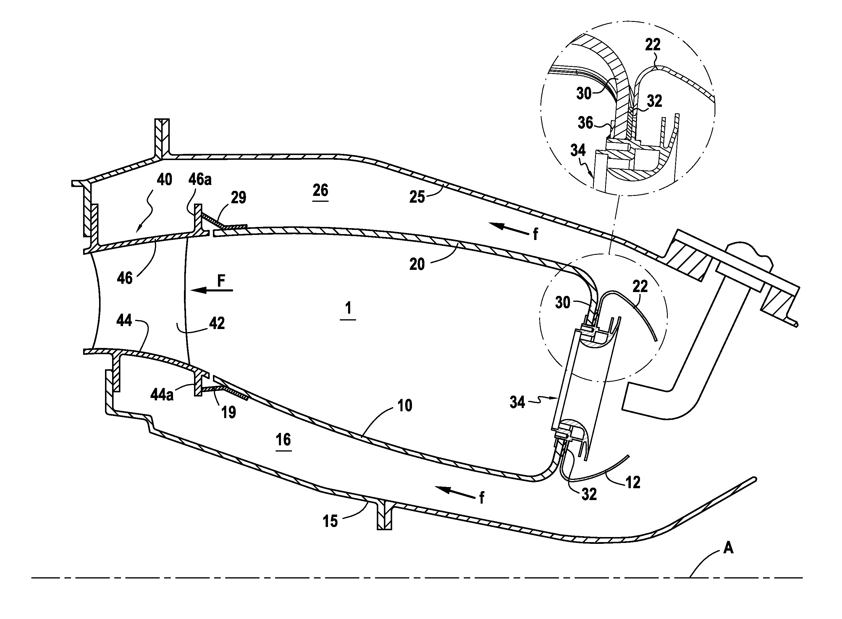
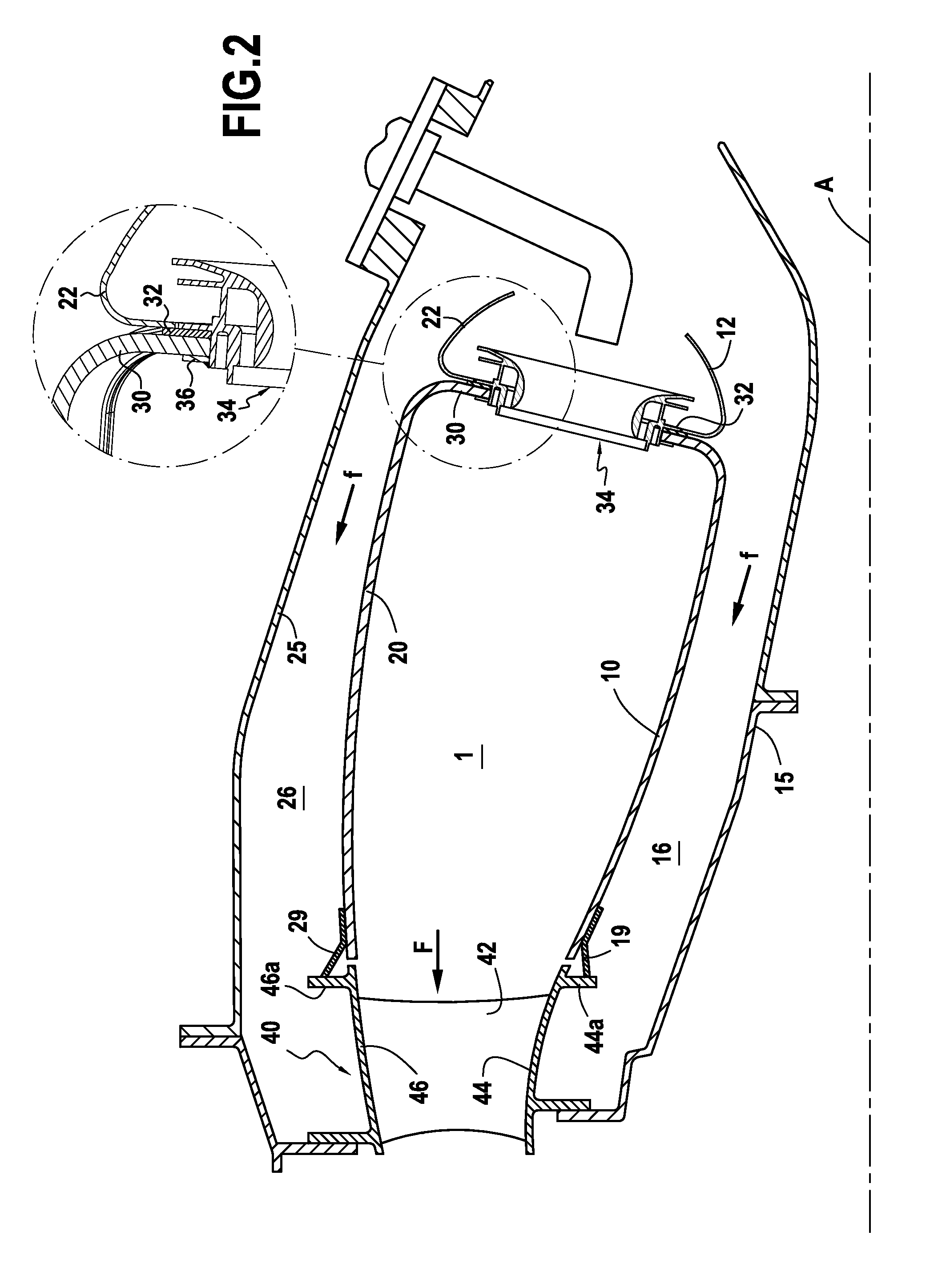
[0028]As shown very diagrammatically in FIG. 2, the combustion chamber 1 is of annular shape about an axis A and it is defined by an inner annular wall 10, an outer annular wall 20, and a chamber end wall 30. The end wall 30 defines the upstream end of the combustion chamber and presents openings that are distributed around the axis A for the...


PUM


Abstract

An assembled annular combustion chamber comprises an annular inner wall and an annular outer wall made of ceramic matrix composite material together with a chamber end wall connected to the inner and outer walls and provided with orifices for receiving injectors. Elastically-deformable link parts connect the inner wall and the outer wall of the chamber to inner and outer casings that are made of metal. The assembly formed by the inner wall, the outer wall, and the combustion chamber end wall is subdivided circumferentially into adjacent chamber sectors, each sector being made as a single piece of ceramic composite material and comprising an inner wall sector, an outer wall sector, and a chamber end wall sector. The link parts connect the inner metal casing and the outer metal casing respectively to each inner wall sector of the combustion chamber and to each outer wall sector of the chamber. The chamber end wall sectors are in contact with a one-piece ring to which they are connected.

Description

BACKGROUND OF THE INVENTION[0001]The invention relates to gas turbines and more particularly to the configuration and the assembly of an annular combustion chamber having walls made of ceramic matrix composite (CMC) materials. The fields of application of the invention comprise gas turbine aero-engines and industrial gas turbines.[0002]Proposals have been made to use CMCs for making gas turbine combustion chamber walls because of the thermostructural properties of CMCs, i.e. because of their ability to conserve good mechanical properties at high temperatures. Higher combustion temperatures are sought in order to improve efficiency and reduce the emission of polluting species, in particular for gas turbine aero-engines, by reducing the flow rate of air used for cooling the walls. The combustion chamber is mounted between inner and outer metal casings by means of link elements that are flexible, i.e. elements that are elastically deformable, thus making it possible to absorb the diffe...

Claims


Application Information

Patent Timeline
Patent Type & Authority Patents(United States)
IPC IPC(8): F23R3/50
CPCF23R3/002F23R3/007F23R3/50F23R3/60F23M2900/05005F23R2900/00005F23R2900/00012F23R2900/00018F02C3/14F23R3/42
Inventor HABAROU, GEORGESCAMY, PIERRECARRERE, BENOITBOUILLON, ERIC
Owner SN DETUDE & DE CONSTR DE MOTEURS DAVIATION S N E C M A
Why Eureka
Try Eureka