Bi-material composite structure with reduced thermal expansion

a composite structure and composite material technology, applied in the direction of cosmonautic thermal protection, machines/engines, cosmonautic vehicles, etc., can solve the problems of one-dimensional thermal stability, complex pin-jointed design, and design challenges

Inactive Publication Date: 2012-03-27
AIR FORCE UNITED STATES OF AMERCIA THE AS REPRESENTED BY THE SEC OF THE
View PDF12 Cites 22 Cited by
  • Summary
  • Abstract
  • Description
  • Claims
  • Application Information

AI Technical Summary

Benefits of technology

[0010]A planar two material structure comprising a first material having a coefficient of thermal expansion greater than 0 and a second material having a second coefficient of thermal expansion greater than 0. In one embodiment the two materials structurally combined in a plurality of repetitive four or six sided cells. Where the structure is equilateral triangles having three sides of equal length and three equal included

Problems solved by technology

Prior attempts to design stable structures for this type application resulted in only one-dimensional thermal stability and required complex pin-jointed designs.
Another class of design challenge arises in structures subjected to space-varying thermal gradients, such as engine components subjected to hot combustion environment or hypersonic airframe surfaces subjected to aerothermal heating.
The resulting gradient in thermal strain can result in design-limiting thermally induced stressing.
The ‘menu’ of intrinsic CTE's available with structural engineering materials is however quite limited, and in most cases, available materials with the ideal expansivity for an application are less than ideal for other reasons.
For example, int

Method used


Image

  • Bi-material composite structure with reduced thermal expansion
  • Bi-material composite structure with reduced thermal expansion
  • Bi-material composite structure with reduced thermal expansion

Examples


Embodiment Construction

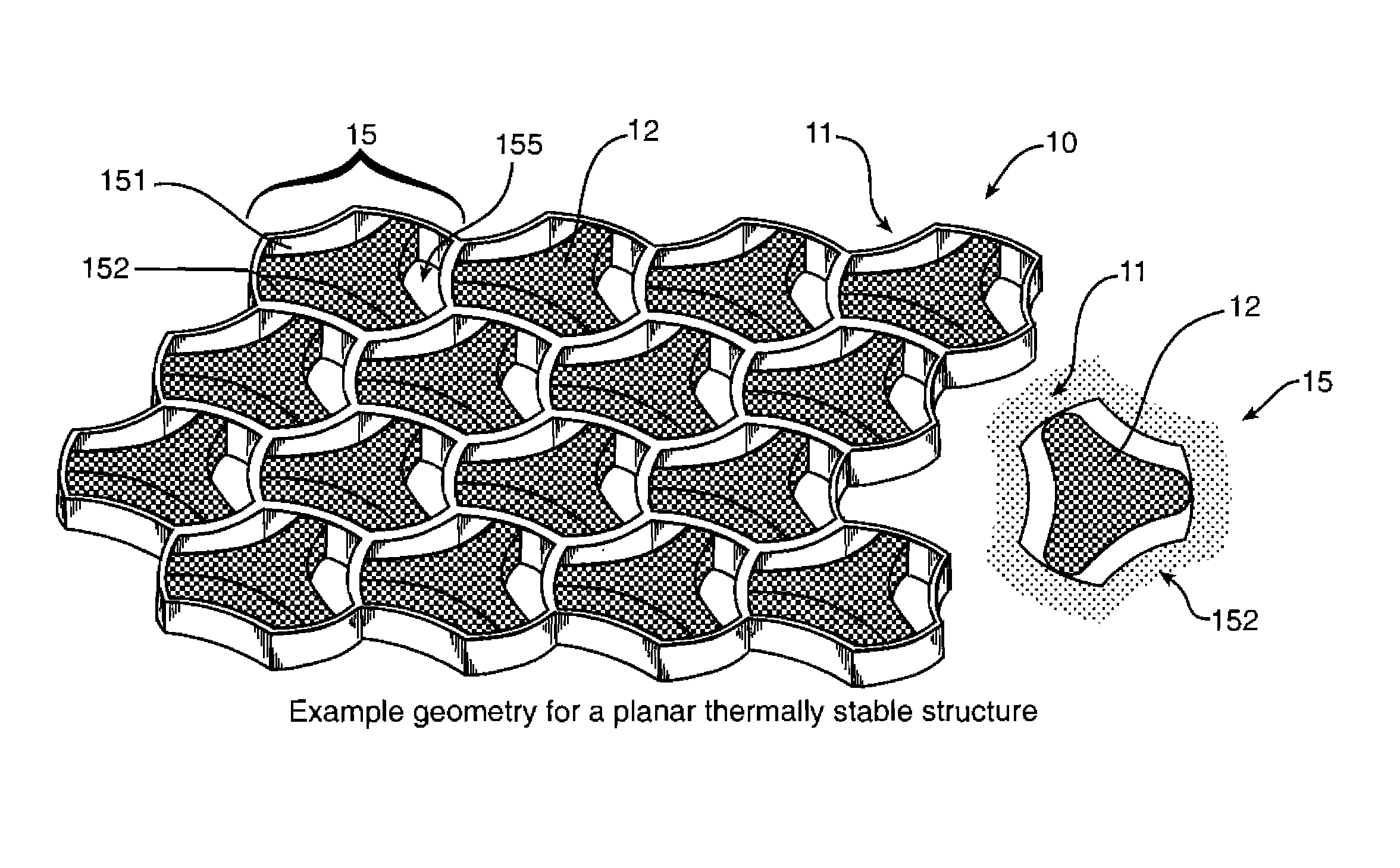
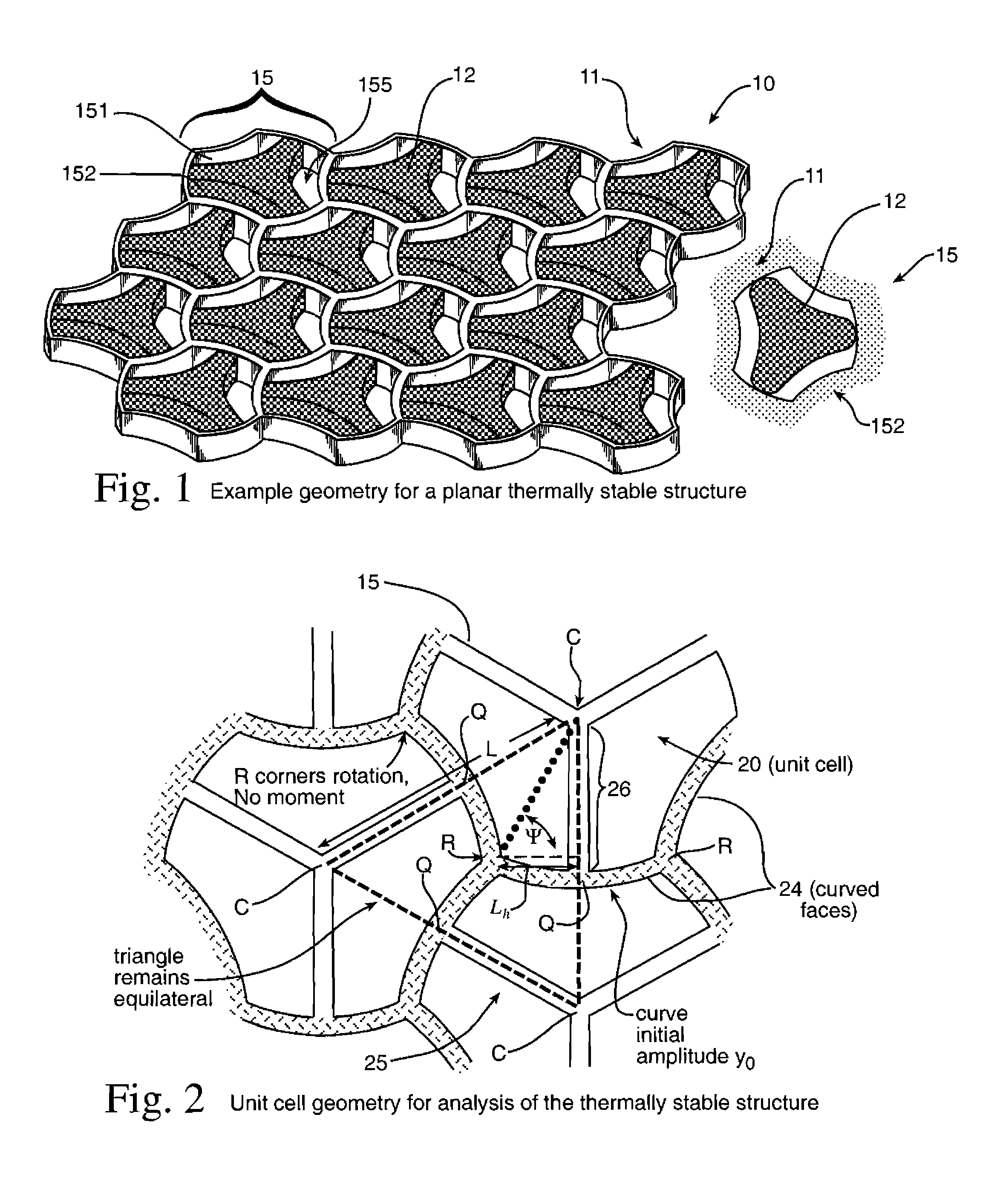
[0062]An example of a thermal structure 10 is shown in FIG. 1. A continuous honeycomb structure 11 is fabricated of one material. The material may have a coefficient of thermal expansion greater than 0.0. The honeycomb structure 11 includes a plurality of cells 15, which have cell sides 151 forming a cell opening 155. The cells 15 also have a top surface 152. An insert 12 made of preferably a second material with preferably a different Coefficient of thermal expansion (CTE) also greater than 0.0 is inserted in the cell opening 155 or formed as part of each cell 15. Preferably the CTE of the insert 12 material is greater than the CTE of the honeycomb structure 11 material. The inserts 12 may be permanently bonded or simply press-fit, therefore allowing flexibility to design with a wide variety of constituents. The inserts may be flush with the top surface 152, below the top surface 152 or in alternate embodiments extend above the cell top surface 152. In alternate embodiments the ins...


PUM

PropertyMeasurementUnit
Angleaaaaaaaaaa
Temperatureaaaaaaaaaa
Structureaaaaaaaaaa

Abstract

A planar two material structure comprising a first material having a coefficient of thermal expansion greater than zero and a second material having a second coefficient of thermal expansion greater than zero. The two materials structurally combined in a plurality of repetitive for or six sided unit cells having a combined coefficient of thermal expansion less than the coefficient of thermal expansion of either material alone.

Description

RIGHTS OF THE GOVERNMENT[0001]The invention described herein may be manufactured and used by or for the Government of the United States for all governmental purposes without the payment of any royalty.BACKGROUND OF THE INVENTION[0002]The invention relates to the design of structures with near zero thermal expansion or other design-specific thermal shape change characteristics using materials which, although desirable for other reasons, would not be acceptable with conventional single-material structural design because their intrinsic thermal expansivity doesn't match the design criteria.[0003]In the design of most engineering structures which are subject to significant temperature excursions, the thermal expansion behavior of the structure is of key importance. The constituent material's coefficient of thermal expansion (CTE) is one of the driving material properties considered in the engineering materials selection process. The importance of the thermal expansion stems from several...

Claims


Application Information

Patent Timeline
IPC IPC(8): B32B3/12
CPCB64G1/22B64G1/66B64G1/58F01D5/282F01D5/284Y10T428/1234F05D2250/283F05D2300/5021Y10T428/24149Y10T428/24165Y10T428/24157F05D2300/6033
Inventor JEFFERSON, GEORGEKERANS, RONALD J.PARTHASARATHY, TRIPLICANE A.
Owner AIR FORCE UNITED STATES OF AMERCIA THE AS REPRESENTED BY THE SEC OF THE
Why Eureka
Try Eureka