Method and apparatus using non-contact measuring device to determine rail distance traveled

a non-contact, measuring device technology, applied in the direction of distance measurement, railway signalling and safety, devices using time traversed, etc., can solve the problems of reduced visibility, insufficient accuracy, environmental problems, etc., and achieve accurate calculation of velocity, high noise, and high speed

Inactive Publication Date: 2012-04-03
SYST & MATERIALS RES
View PDF8 Cites 4 Cited by
  • Summary
  • Abstract
  • Description
  • Claims
  • Application Information

AI Technical Summary

Benefits of technology

The system achieves high accuracy with a standard deviation of 2-3 ft / mile, maintaining precision at higher speeds and in various environmental conditions, avoiding mechanical errors associated with wheel-based measurements.

Problems solved by technology

Rail-distance-traveled estimates are typically based on a tachometer approach or via GPS, but such systems do not provide sufficient accuracy.
Doppler radar and pulse generator systems are more accurate but have environmental problems in extreme conditions.
Laser based systems must have an optically clear path to the reflecting surface, and reduced visibility due to snow accumulation or similar conditions are problematic challenges to accurate measurement.
Measurement techniques relying on wheel rotation are also known, but these techniques suffer from error due to wheel slippage, wheel wear, and a number of other factors.

Method used


Image

  • Method and apparatus using non-contact measuring device to determine rail distance traveled
  • Method and apparatus using non-contact measuring device to determine rail distance traveled
  • Method and apparatus using non-contact measuring device to determine rail distance traveled

Examples


Embodiment Construction

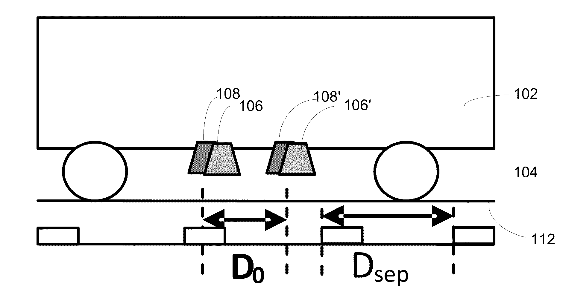
[0023]Preferred embodiments of the invention use a non-contact, distance traveled measurement system (DTMS) to calculate speed and distance traveled by a vehicle over rails—more specifically, by trains traveling on standard railroad tracks. Preferably, a pair of short range (near field) microwave-based transmitters / sensors (transceivers) are mounted on the underside of the train and used to key on rail-bed features such as cross ties or tie plates. Reflected microwave energy from two transceivers at a fixed distance apart is correlated to determine the time delay between the first and second transceiver passage. From this time delay, nearly instantaneous velocity can be computed at each given target such as a tie plate (metal target) or a tie (dielectric contrast target). These velocities can be estimated, for example, every 8636 microseconds at 125 mph for a 19″ tie to tie distance. Velocity versus time curves can be integrated over time to derive distance traveled.

[0024]According ...


PUM


Abstract

A non-contact, distance traveled measurement system (DTMS) to calculate speed and distance traveled by a vehicle over rails—more specifically, by trains traveling on standard railroad tracks. Preferably, a pair of short range (near field) microwave-based transmitters / sensors (transceivers) are mounted on the underside of the train and used to key on rail-bed features such as cross ties or tie plates. Preferred embodiments also include infrared sensors as a redundant channel that is less sensitive to moisture in the track bed. Data from the sensors is correlated to determine the time delay between the first and second sensors' passage over objects on the rail bed such as cross-ties or tie-plates. From this time delay, nearly instantaneous velocity can be computed at each given target such as a tie plate (metal target) or a tie (dielectric contrast target). Velocity versus time curves can be integrated over time to derive distance traveled.

Description

[0001]This application claims priority of U.S. Provisional Application 61 / 255,371, filed Oct. 27, 2009, and is hereby incorporated by reference.STATEMENT REGARDING FEDERALLY SPONSORED RESEARCH OR DEVELOPMENT[0002]This invention was made with Government support and the Government has certain rights in the invention.TECHNICAL FIELD OF THE INVENTION[0003]The present invention generally relates to determining the speed and distance traveled by a vehicle over rails, and more specifically, by trains traveling on standard railroad tracks.BACKGROUND OF THE INVENTION[0004]Rail-distance-traveled estimates are typically based on a tachometer approach or via GPS, but such systems do not provide sufficient accuracy. Doppler radar and pulse generator systems are more accurate but have environmental problems in extreme conditions. Laser based systems must have an optically clear path to the reflecting surface, and reduced visibility due to snow accumulation or similar conditions are problematic ch...

Claims


Application Information

Patent Timeline
Patent Type & AuthorityPatents(United States)
IPC IPC(8): G01S13/08
CPCB61L25/021B61L25/026G01C22/02G01P3/66G01P3/68G01S13/605G01S17/58G01S13/865
InventorBRAY, ALAN V.MCNEAL, SEANMCDANIEL, JESSE
OwnerSYST & MATERIALS RES