Method for manufacturing a head suspension

a manufacturing method and head suspension technology, applied in the field of head suspension manufacturing methods, equipment and jigs, can solve the problems of data errors, deterioration of productivity, dispersion of vibration control effect of the head suspension, etc., and achieves the effects of suppressing dispersion, reducing labor intensity, and simplifying man-hour and drive control

Active Publication Date: 2012-04-10
NHK SPRING CO LTD
View PDF7 Cites 30 Cited by
  • Summary
  • Abstract
  • Description
  • Claims
  • Application Information

AI Technical Summary

Benefits of technology

[0011]An object of the present invention is to provide a method, apparatus and jig for manufacturing a head suspension, capable of suppressing dispersion in a vibration control effect of the head suspension and improving productivity of the head suspension, and is to provide a manufactured head suspension.
[0014]Namely, in comparison with a case of a manufacturing process where, for example, the punched-out vibration damper pieces aligned once on the liner are picked up and stuck on the objective portion one by one, it can simplify man-hour and drive control for handling of the vibration damper piece to carry out the positioning for attaching the vibration damper piece with high degree of accuracy. This results in suppressing dispersion in a vibration control effect of the head suspension.
[0015]At the same time, it can prevent the vibration damper piece from scattering and being lost before happens, and can improve the productivity.

Problems solved by technology

In such head suspension, data errors occur due to off tracks that are generated by turbulence (wind excitation), a natural vibration or the like at rotation of the disc for reading or writing of a signal.
However, according to the investigation by the inventors of the present invention, when a manufacturing process of the head suspension includes a hand working, it results in dispersion of a vibration control effect of the head suspension and deteriorates productivity.

Method used


Image

  • Method for manufacturing a head suspension
  • Method for manufacturing a head suspension
  • Method for manufacturing a head suspension

Examples


Embodiment Construction

[0023]A method, apparatus and jig for manufacturing a head suspension, and a manufactured head suspension according to an embodiment of the present invention are described in detail hereafter with reference to drawings.

[0024]First, the apparatus and jig used for the method for manufacturing the head suspension according to an embodiment of the present invention is described.

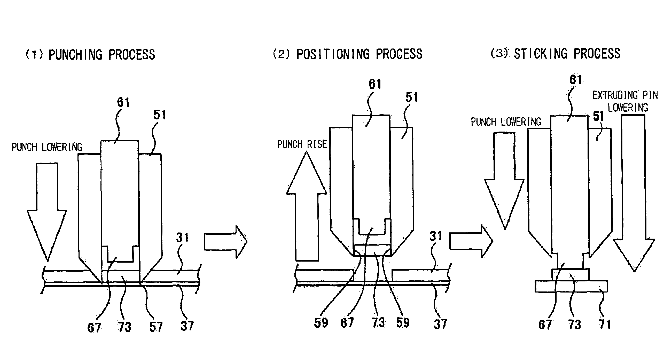
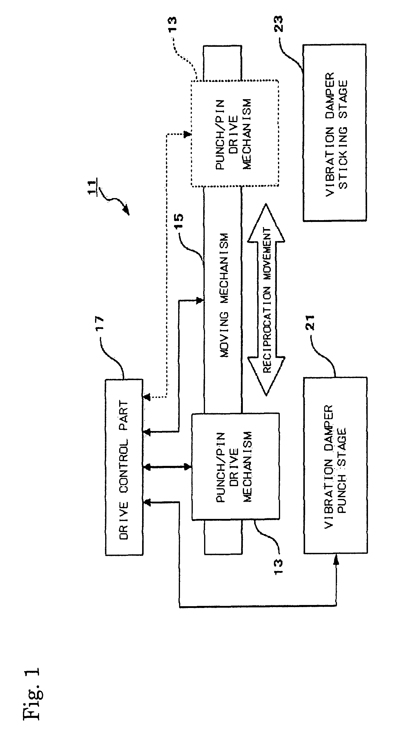
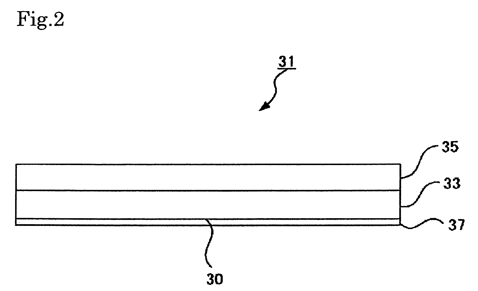
[0025]FIG. 1 is a schematic functional block diagram showing the head suspension manufacturing apparatus (apparatus for manufacturing the head suspension), FIG. 2 is a side view of a vibration damper base material to be stuck on a head suspension. FIGS. 3(1) to (3) are views in which FIG. 3(1) shows a punch, FIG. 3(2) shows a extruding pin and FIG. 3(3) shows a state of use of the punch and the extruding pin as the manufacturing jig (jig for manufacturing the head suspension). FIG. 4 is a perspective view showing the head suspension to which a vibration damper piece is attached.

[0026]As shown in FIGS. 1 to 4, the...


PUM

PropertyMeasurementUnit
thicknessaaaaaaaaaa
thicknessaaaaaaaaaa
thicknessaaaaaaaaaa

Abstract

A method for manufacturing a head suspension is capable of suppressing the dispersion in the vibration control effect of a head suspension and improve productivity, the manufacturing method includes a step of punching, by use of a hollow punch having a tooth portion at a distal end thereof, a vibration damper piece out from a base material having a vibration damper provided detachably on a liner through an attaching surface, to hold the vibration damper piece on a hollow internal surface of the punch, a step of positioning the punch holding the vibration damper piece on an objective portion of a semi-finished head suspension, and a step of attaching, by use of an extruding implement, the vibration damper piece on the objective portion with the attaching surface through extruding the vibration damper piece from the punch.

Description

BACKGROUND OF THE INVENTION[0001]1. Field of the Invention[0002]The present invention relates to a method, apparatus and jig for manufacturing a head suspension that supports a magnetic head slider of a magnetic disk device, and relates to a manufactured head suspension. In particular, the invention relates to the method, apparatus and jig for manufacturing the head suspension, capable of automating a process to attach a vibration damper on an objective part of a semi-finished head suspension to suppress dispersion in a vibration control effect of the head suspension and improve productivity, and relates to the manufactured head suspension.[0003]2. Description of the Related Art[0004]A head suspension for supporting a magnetic head slider (hereinafter, abbreviated as a “slider”) is provided in a magnetic disk device (HDD). The head suspension has a base plate, a load beam attached to the base plate and a flexure attached to the load beam.[0005]In such head suspension, data errors oc...

Claims


Application Information

Patent Timeline
Patent Type & Authority Patents(United States)
IPC IPC(8): G11B5/127H04R31/00
CPCG11B5/4813G11B5/4826G11B5/4833Y10T29/53165Y10T29/5313Y10T29/49032Y10T29/4903Y10T29/49027Y10T29/49025
Inventor TSUTSUMI, KUNIHIROAMEMIYA, TSUYOSHI
Owner NHK SPRING CO LTD
Why Eureka
Try Eureka