Air intake apparatus

a technology of air intake apparatus and air filter element, which is applied in the direction of filtration separation, combustion-air/fuel-air treatment, and separation processes, etc., can solve the problems of time-consuming cleaning, air filter element fouling, and air filter element contamination on the cited known air intake assembly, so as to reduce the tool-up time, increase the surface area, and reduce the contamination of the air filter element

Active Publication Date: 2012-04-10
KTM AG
View PDF21 Cites 10 Cited by
  • Summary
  • Abstract
  • Description
  • Claims
  • Application Information

AI Technical Summary

Benefits of technology

[0013]The air intake apparatus in accordance with the present disclosure thus is characterized in that, among other things, the air filter element can be removed out of the case without the aid of a tool, in thereby performing a movement that is guided by apparatus elements and whereby the filter element remains located on the overall apparatus. During filter cleaning the apparatus is hinged open from the case, meaning that together with being hinged open, or by a rotating movement, the air filter element can be moved out of the case housing it, without requiring the assistance of a tool.
[0029]It also is provided that the case has, at an end portion opposite a duct fluidly communicating in the longitudinal direction of the case, an air intake snorkel for fluidly communicating ambient air into the case. To reduce debris being entrained into the case it is provided for in yet another aspect of the disclosed apparatus that the air intake snorkel is configured for arrangement in the region below a rider saddle of the vehicle. Although ambient air to be cleaned gains access to the case via this air intake snorkel, because the air intake snorkel is arranged below the rider saddle of the vehicle, it is ensured that the ambient air passing through the air intake snorkel entrains less debris than would be the case, for example, were the air intake snorkel to be located fully exposed uncovered without protection.

Problems solved by technology

This gap results in debris such as dirt, sand and / or grit thrown up by the rear wheels gaining access to the case through the gap, quickly fouling up the air filter element.
Cleaning the air filter element on the cited known air intake assemblies is impossible without the aid a tool.
Moreover, cleaning is time-consuming because every time bolts must first be loosened before, in a next step, the air filter element can be removed from its case.

Method used


Image

  • Air intake apparatus
  • Air intake apparatus
  • Air intake apparatus

Examples


Embodiment Construction

Best Mode for Practicing the Invention

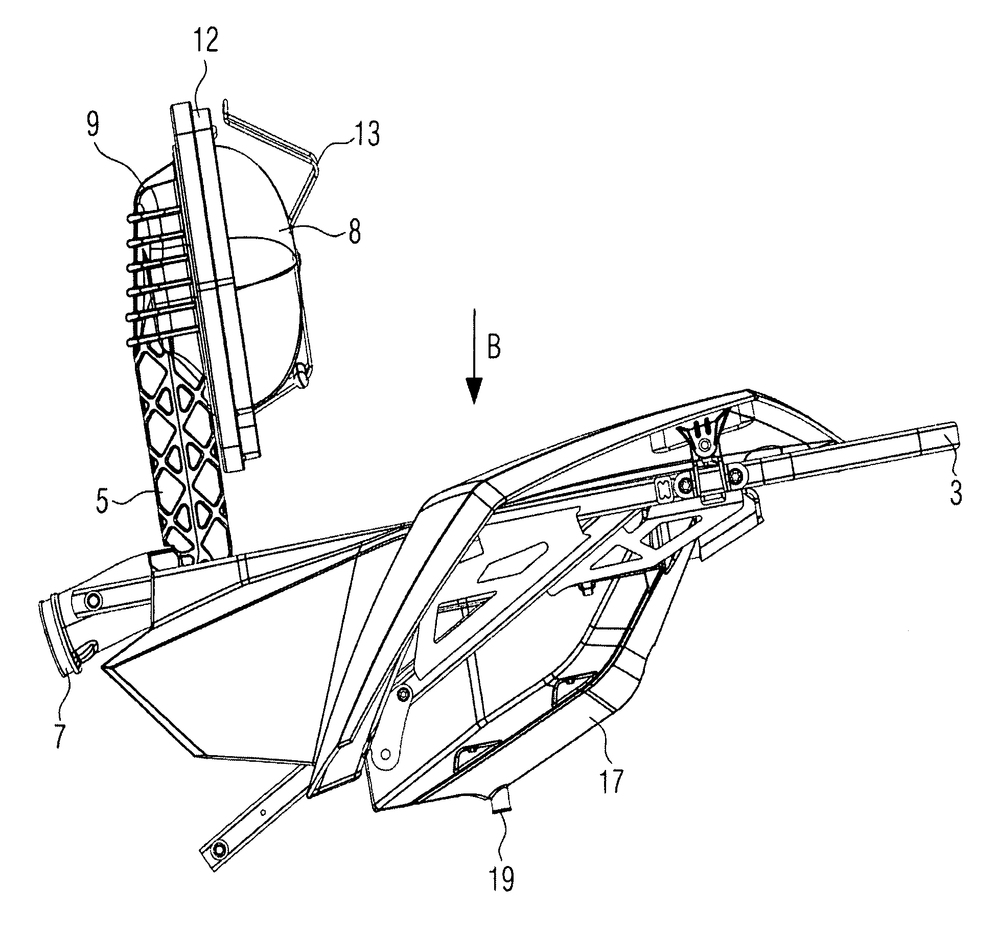
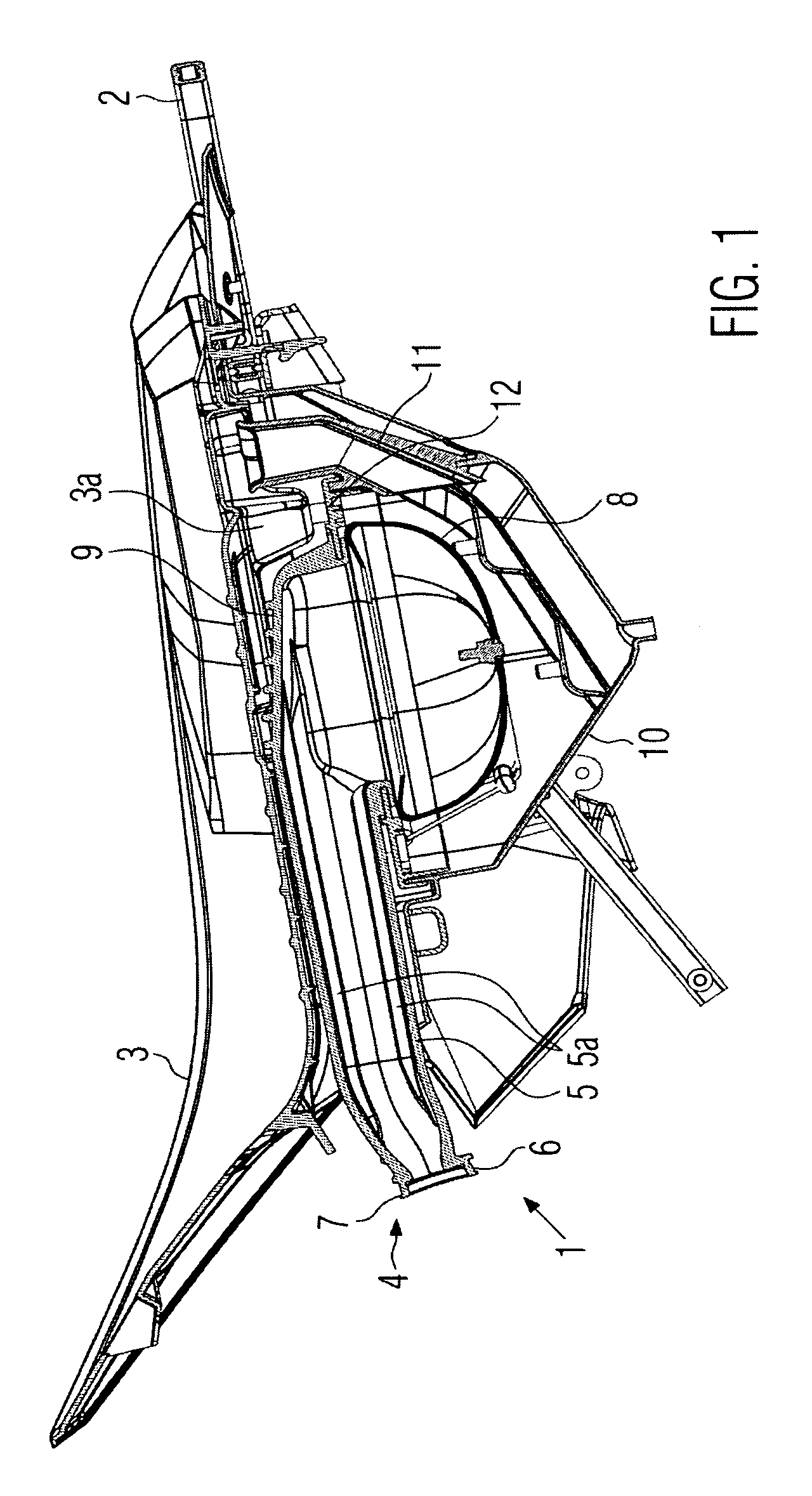
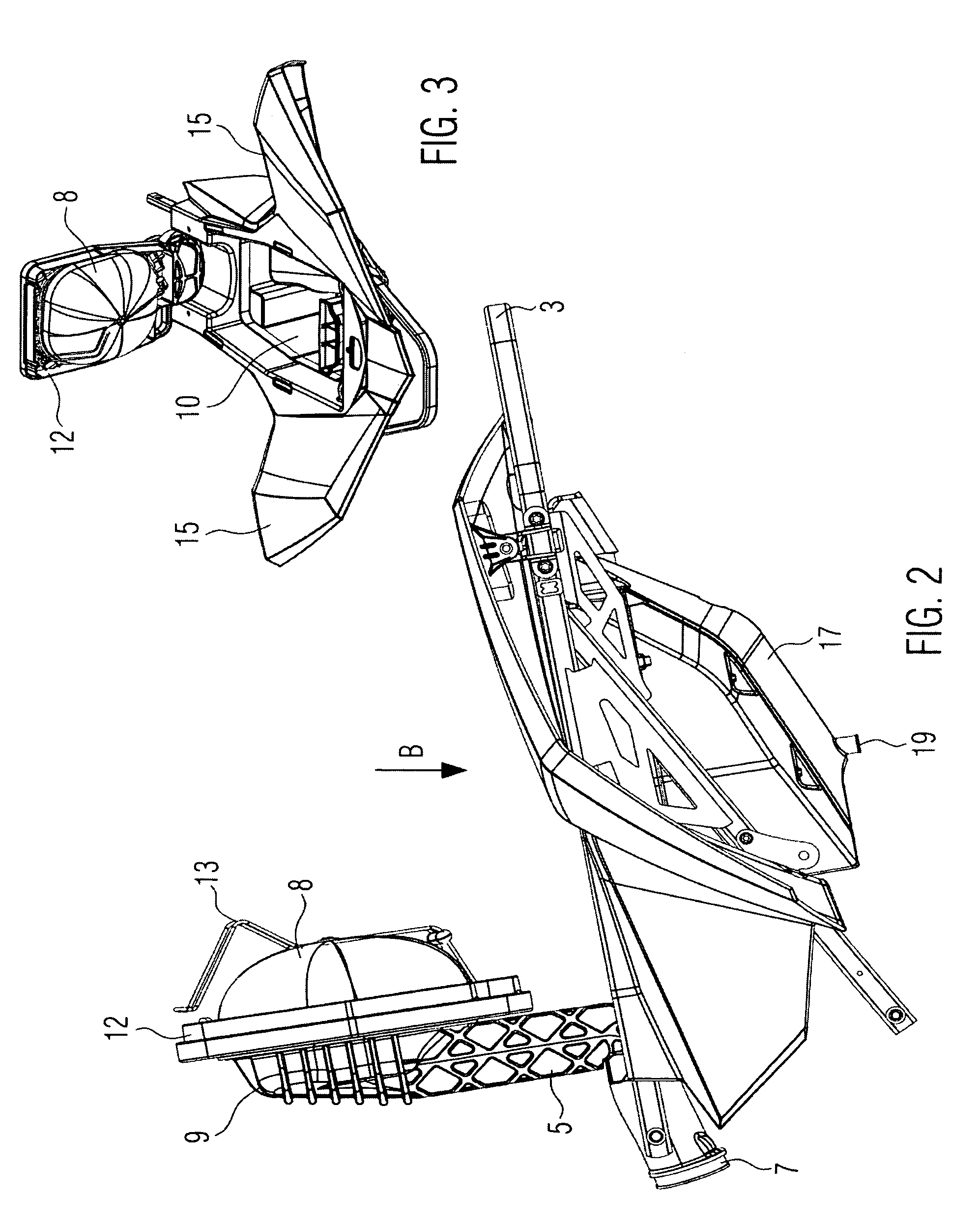
[0038]Referring now to FIG. 1 of the drawings, there is illustrated a section view of an air intake apparatus 1 in accordance with one embodiment of the present disclosure arranged on a frame structure 2 of an ATV.

[0039]Located at the frame structure 2 is a rider saddle 3 for a rider of the ATV. As is directly evident, the air intake apparatus 1 in the embodiment as shown is arranged beneath the saddle 3, so that the air intake apparatus 1 is already located where it is protected from dirt and water splash. For fluidly communicating cleaned intake air in the direction of the internal combustion engine (not shown), the air intake apparatus 1 comprises a communicating means 4 including a flexibly configured duct 5 via which cleaned intake air can be transported. At its end portion 6 facing the internal combustion engine, the duct 5 is engineered with a coupling 7 which is connectable to a throttle member or carburetor member of the internal combus...


PUM

PropertyMeasurementUnit
angleaaaaaaaaaa
flexibleaaaaaaaaaa
frame structureaaaaaaaaaa

Abstract

An air intake apparatus for a vehicle powered by an internal combustion engine. There is disclosed an air intake apparatus including ducting members for fluidly communicating cleaned intake air, for combustion, in the direction of the internal combustion engine. The apparatus also features an air filter element arranged on the duct members, as well as a case for housing the air filter element. The communicating duct members are engineered such that the air filter element can be pivoted from the case to an open position, such as for cleaning, while nevertheless remaining upon on the air communicating duct members.

Description

CROSS-REFERENCE TO RELATED APPLICATIONS[0001]This application claims priority to German Patent Application No. DE 10 2007 021 756.2, filed on May 9, 2007, the entirety of which is incorporated herein by reference.BACKGROUND OF THE INVENTION[0002]1. Field of the Invention[0003]The present invention relates to air intake apparatuses for vehicles powered by an internal combustion engine, and more specifically to an air intake apparatus including elements for fluidly communicating cleaned intake air in the direction of the engine for combustion therein, an air filter element, and a case housing the air filter element.[0004]2. Background Art[0005]Any vehicle comprising an internal combustion engine usually features an air intake apparatus for supplying air to the engine for combustion. The air intake apparatus typically includes an air filter element serving to clean the intake air to remove debris in the form of dirt, water, sand, grit and the like from the intake air in passing through...

Claims


Application Information

Patent Timeline
Patent Type & Authority Patents(United States)
IPC IPC(8): B01D46/00
CPCB01D46/0015B01D46/008B62K5/01B62K5/027F02M35/0203F02M35/0209F02M35/02425F02M35/048F02M35/10137F02M35/10144F02M35/162F02M35/084B01D46/88
Inventor MATSCHL, GERALDGUSTAFSON, TORBJORN
Owner KTM AG
Why Eureka
Try Eureka