
Disk separator plates and method of making disk separator plates for hard disk drives

a technology of hard disk drives and separator plates, which is applied in the field of disk separator plates, can solve the problems of increasing noise, increasing noise, and decreasing hdd performance, and achieving the effects of less debris, less weight, and less cost of production

Active Publication Date: 2016-05-19
INTRL PLEX TECH INC
View PDF16 Cites 1 Cited by
  • Summary
  • Abstract
  • Description
  • Claims
  • Application Information

AI Technical Summary

Benefits of technology

This approach reduces material usage, manufacturing costs, and weight, while providing precise dimensional control and alignment, resulting in a more cost-effective and accurately dimensioned disk separator plate.

Problems solved by technology

This generates undesired noise in the hard disk drive assembly.
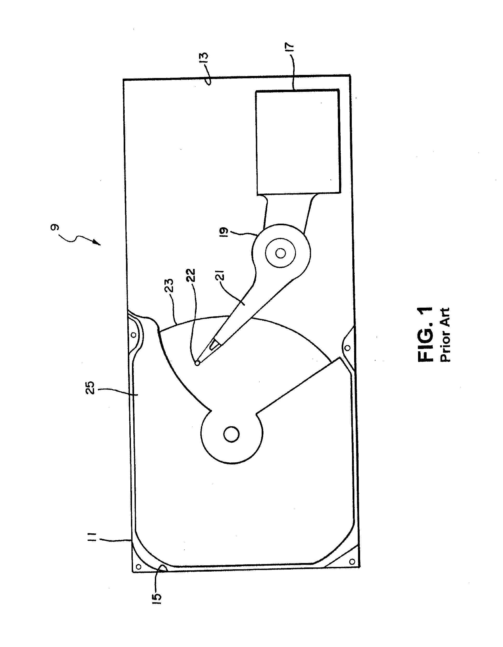
It has been experimentally proven that the main airflow in a hard disk drive assembly, which is tangential to the circumferential edge of the rotating disks causes vortexes to be created between the airflow fluid layers, causing disk flutter and vibration of the magnetic reading heads during operation, thereby increasing noise and decreasing HDD performance.
This increased use of disk separator plates in a hard disk drive increases the cost of the disk drive because of the increased raw materials required, and the secondary manufacturing operations required to make the disk separator plates, after initial stamping, forging, extrusion or casting.
Furthermore, the ability to produce separator plates to precise dimensional control is difficult for each of the above described methods of manufacture.
The plastic injection molding process has special problems associated with it.
The method produces voids and anisotropies in the product.
The major problem with the metal disk separator plates is the cost of manufacturing such plates.
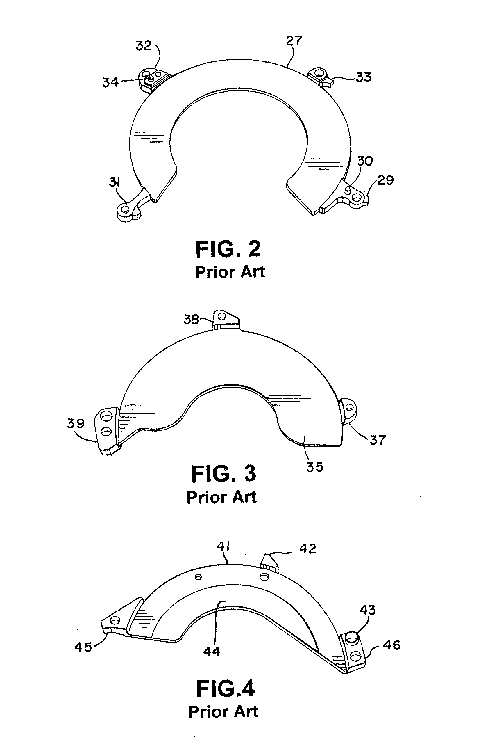
As can be seen by the structure of the offset 56 of separator plate 49, for example, the machining required after initial manufacturing is significant and increases the cost of each separator plate.
Although flat stamped disk separator plates provide the best dimensional control, of all these manufacturing processes, at a minimum manufacturing cost, the stamping process cannot create the thickness, or material reduction required in a typical offset at the mounting points for the disk separator plate.

Method used


Image

  • Disk separator plates and method of making disk separator plates for hard disk drives
  • Disk separator plates and method of making disk separator plates for hard disk drives
  • Disk separator plates and method of making disk separator plates for hard disk drives

Examples


Embodiment Construction

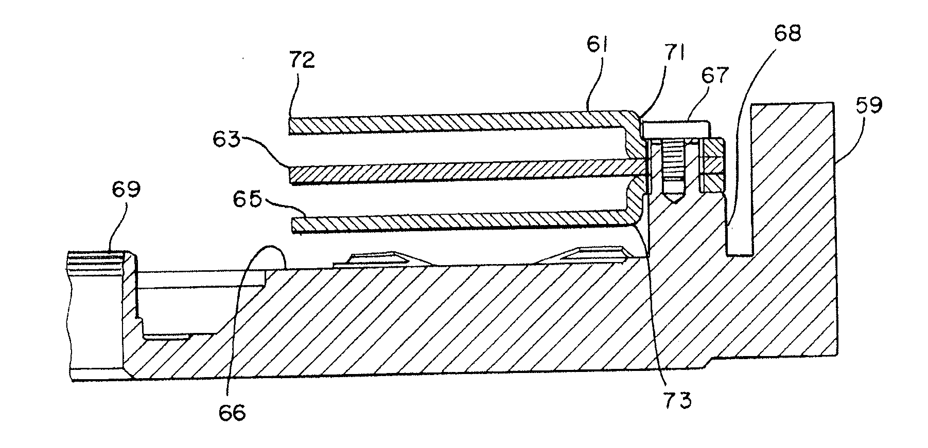
[0044]FIG. 6 illustrates a stack of separator plates 61, 63, 65, manufactured according to the present invention, attached to a housing 59 of a hard disk drive. The upper separator plate 61 and the lower separator plate 65 create the required offset between separator plates 61 and 63, 63 and 65, and 65 and the base 66 respectively, by offset forming the ends of the separator plate 61 and 65 a certain distance to create the offset 71 for separator plate 61 and the offset 73 for separator plate 65. The center separator plate 63 is not bent and has no offset. The stack of separator plates 61, 63, and 65, is assembled on a standoff 68 which is part of the frame 59 of the hard disk drive housing. The stack is fastened down by a fastening bolt 67.

[0045]The disks (not shown) that rotate in the spaces between the separator plates 61 and 63, 63 and 65 and 65 and the base 66, are attached to a rotating spindle 69, in a manner well known.

[0046]Manufacturing the separator plates of FIG. 6 by st...


PUM

PropertyMeasurementUnit
heightaaaaaaaaaa
distanceaaaaaaaaaa
gapaaaaaaaaaa

Abstract

A hard disk drive with a multiple disk stack normally utilizes disk separator plates near the disk surfaces to reduce wind induced vibrations in the disks and the read / write heads. The manufacturing methods currently used to make these separator plates, metal casting and machining, or injection molded plastic, or extruding and machining, or cold forging tends to be expensive and creates unwanted weight and bulk without the desired precision. Stamping disk separator plates from metal provides exceptional dimensional control at reduced cost, but cannot readily provide the thicknesses required. Stamping and extruding the offsets, or stamping and folding the offsets, is a manufacturing process that provides the required dimensions for the offsets, and dimensional control and reduced cost.

Description

CROSS REFERENCE TO RELATED APPLICATIONS[0001]This application is a division of application Ser. No. 13 / 893,107 filed May 13, 2013 for DISK SEPARATOR PLATES AND METHOD OF MAKING DISK SEPARATOR PLATES FOR HARD DISK DRIVES.BACKGROUND OF THE INVENTION[0002]1. Field of the Invention[0003]The present invention relates to disk separator plates for reducing airborne noise and vibration in hard disk drives, and more particularly, pertains to methods of manufacturing disk separator plates.[0004]2. Description of Related Art[0005]It has been common practice for hard disk drives (HDD) to incorporate disk separator plates in order to reduce vibration caused by wind created by the rotating disk surfaces. This generates undesired noise in the hard disk drive assembly. It is thought that the disk separator plates should cover a maximum of the disk surfaces in order to minimize these vibration effects. It has been experimentally proven that the main airflow in a hard disk drive assembly, which is ta...

Claims


Application Information

Patent Timeline
Patent Type & Authority Applications(United States)
IPC IPC(8): G11B23/00
CPCG11B23/0035B21K1/76G11B33/148Y10T29/49908Y10T428/12368B21D22/02
Inventor HOW, LEONG WENGSCHMIDT, RYAN JOHNSTROMBERG, MICHAEL JOHNBRINK, DAMON DOUGLAS
Owner INTRL PLEX TECH INC
Learn More