
Dual color/dual function focal plane

a focal plane and color technology, applied in the direction of optical radiation measurement, direction/deviation determining electromagnetic systems, instruments, etc., can solve the problems of slow tracking update rate, inability to achieve optimal detection and tracking, difficult and computationally intensive tracking/detection algorithms, etc., to achieve the effect of removing the requirement for responsivity map testing and calibration

Active Publication Date: 2012-04-10
OCEANIT LAB
View PDF26 Cites 5 Cited by
  • Summary
  • Abstract
  • Description
  • Claims
  • Application Information

AI Technical Summary

Benefits of technology

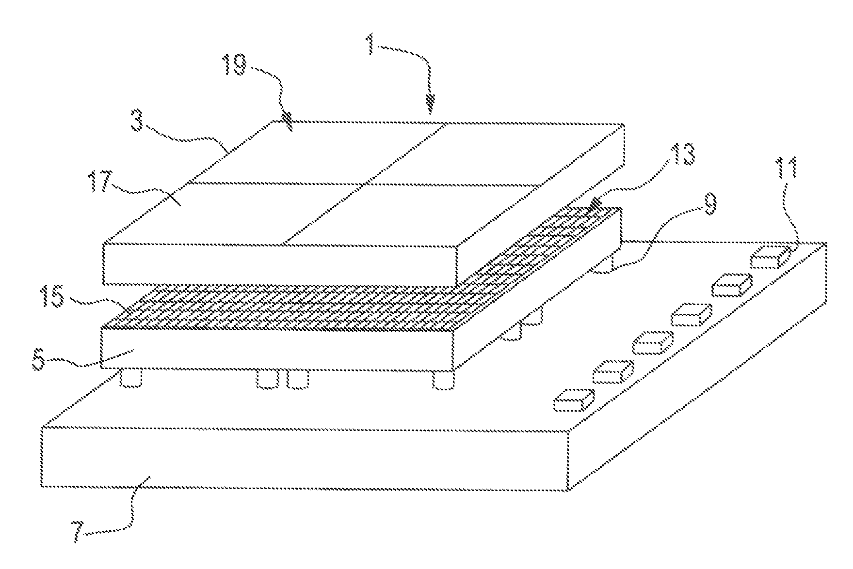
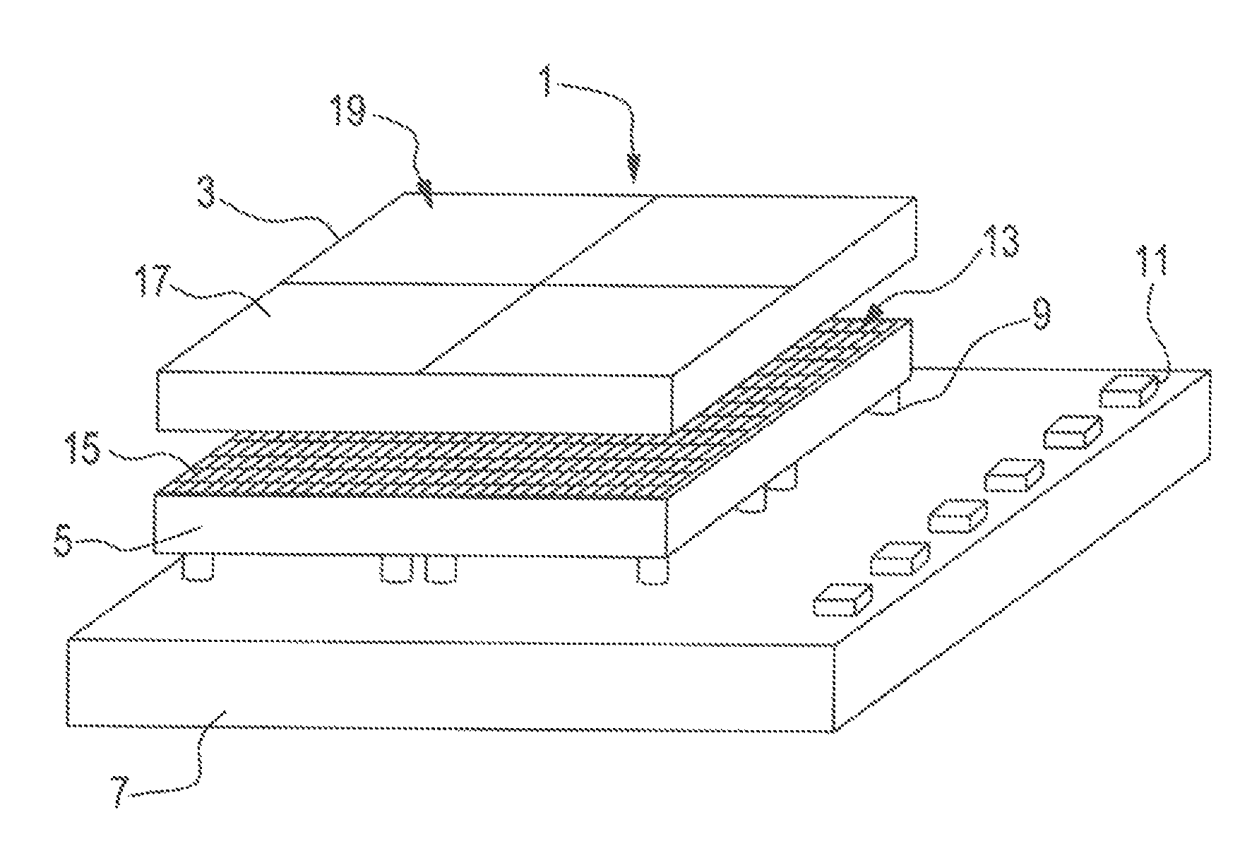
[0013]In one embodiment, a camera control mechanism uses the PSD array's calculation of object location to instruct the camera array to window and zoom, allowing production of images that accurately track objects automatically without any control from off the sensor chip assembly. Pixels of the camera array are directly below cells of the PSD array, creating inherent registration of the PSD cells and eliminating the need for a mechanism to perform responsivity map testing and calibration. The PSD array uses the signal mechanism to signal the camera array to power up when it detects an appropriate change of scene.

Problems solved by technology

Conventional devices primarily use pixel-based cameras for these tasks, but remain deficient for optimal detection and tracking.
Deficiencies include slow tracking update rates, difficult and computationally intensive tracking / detection algorithms, power dissipation, among others.
Some missile seekers use “quad” position sensitive detector (PSD) devices, but these do not provide continuous position location or any type of imaging / discrimination capability.

Method used


Image

  • Dual color/dual function focal plane
  • Dual color/dual function focal plane

Examples


Embodiment Construction

[0017]The invention provides the ability to perform high-speed tracking and detailed imaging (for discrimination and / or any other purpose) in a single system. Specifically, a single focal plane integrated circuit hybrid replaces multiple focal plane circuits and associated off-focal plane signal processing electronics.

[0018]Significant decrease in complexity and component count for multi color object detection, ranging and tracking is provided. The invention also increases the video rate associated with tracking fast moving objects because the control required to change the cameras windowing is generated automatically on focal plane. The invention allows a single system to perform functions that would require at least two systems in conventional devices.

[0019]As shown in FIG. 1, the invention is an optical sensor—a dual function, dual color focal plane PSD sensor chip assembly providing efficient optical detection, ranging, and tracking systems and components.

[0020]The SCA assembly ...


PUM


Abstract

A single focal plane integrated circuit hybrid replaces multiple focal plane circuits and associated off-focal plane signal processing electronics. A dual function, dual color focal plane PSD sensor chip assembly includes a PSD array, a traditional pixelized camera array, a signal processing chip, and flip-chip interconnects and wirebond pads to support electronics on the signal processing chip. The camera array is made of a material sensitive to wavelengths longer than the PSD array material is sensitive to. The PSD array is disposed in the same substrate as the camera array. The PSD array tracks object locations and directs the camera array to window and zoom while capturing images. Inherent registration of PSD cells to the pixelized camera array makes responsivity map testing and spatial calibration unnecessary. Reduction in power dissipation is achieved by powering on the camera array only when the PSD detects a change in scene.

Description

[0001]This application claims the benefit of U.S. Provisional Application No. 60 / 779,890 filed Mar. 8, 2006, which is hereby incorporated by reference in its entirety.BACKGROUND OF THE INVENTION[0002]The invention relates to object detection, tracking and discrimination, including, but not limited to, long range detection and tracking; high-speed tracking and imaging; missile-seeker tracking and discrimination and the like.[0003]Conventional devices primarily use pixel-based cameras for these tasks, but remain deficient for optimal detection and tracking. Deficiencies include slow tracking update rates, difficult and computationally intensive tracking / detection algorithms, power dissipation, among others.[0004]Some missile seekers use “quad” position sensitive detector (PSD) devices, but these do not provide continuous position location or any type of imaging / discrimination capability.[0005]Needs exist for a simple device with enhanced performance that overcomes the shortcomings of ...

Claims


Application Information

Patent Timeline
IPC IPC(8): G01J5/02
CPCG01J3/36F41G7/008F41G7/2253F41G7/2293G01S3/784H04N23/11
Inventor SCOTT, BASILWOLFSHAGEN, RANDY
Owner OCEANIT LAB
Learn More