
Apparatus and method for decreasing bio-effects of magnetic fields

a magnetic field and bio-effect technology, applied in the field of apparatus and a method for decreasing the bio-effect of magnetic field gradients on tissue, can solve the problems of magnetic field gradients, eliciting undesirable responses, electric fields, etc., and achieve the effect of decreasing the duration of scan times for mri

Active Publication Date: 2012-04-10
WEINBERG MEDICAL PHYSICS
View PDF10 Cites 33 Cited by
  • Summary
  • Abstract
  • Description
  • Claims
  • Application Information

AI Technical Summary

Benefits of technology

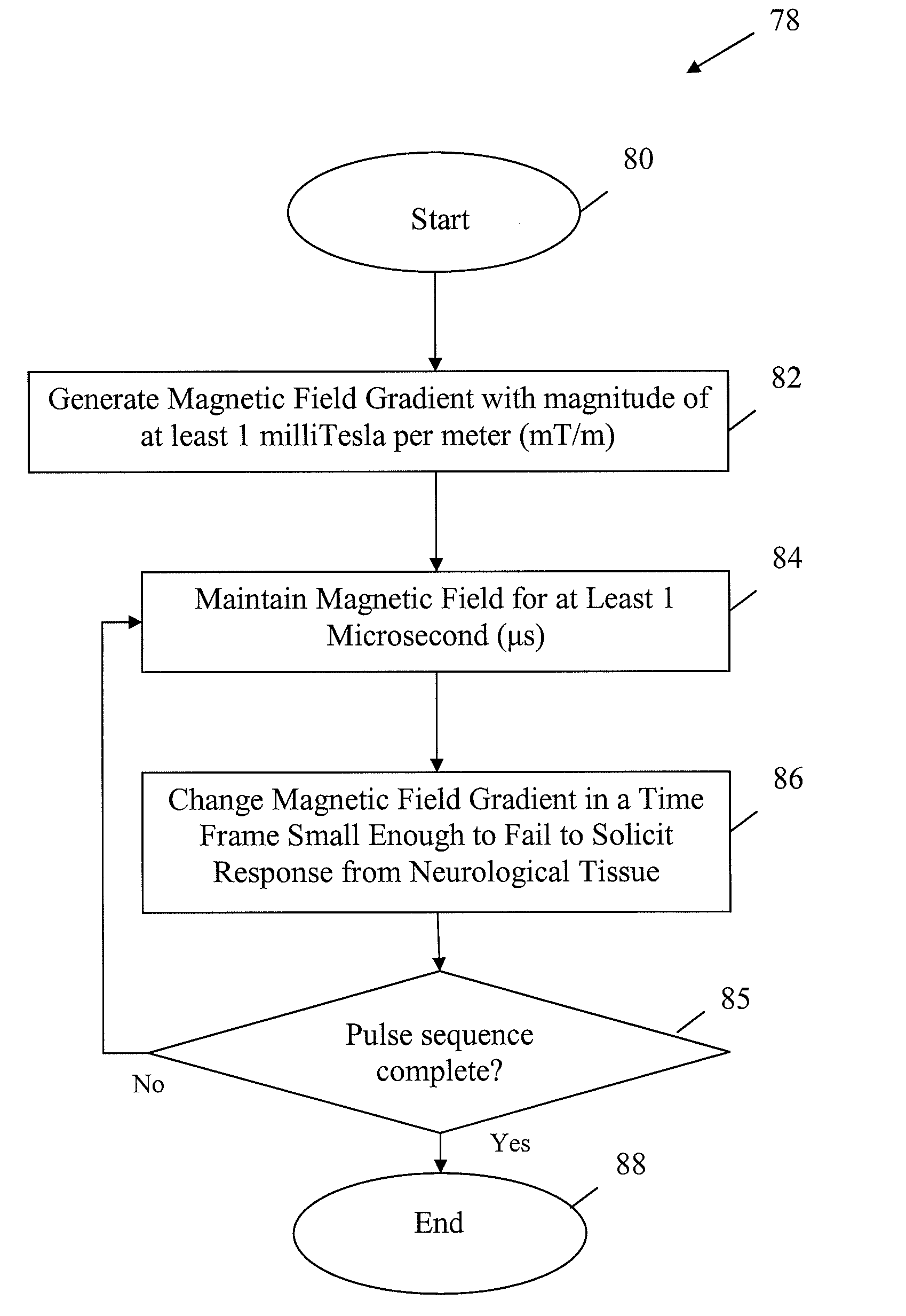
"The present invention provides an apparatus and method for decreasing the duration of scan times for MRI by using magnetic field gradients with a magnitude greater than that traditionally employed. The invention also takes advantage of a physiological loophole to increase the gradient field thresholds without triggering any bio-effects. The invention utilizes solid-state switch and / or PFL technologies that conform to the requirements of MRI gradient amplifiers. The invention further reduces the influence of eddy currents by acquiring signals at long echo time and making the bore of the cryostat significantly larger than the gradient coil. The technical effects of the invention include decreased scan times, improved image quality, and reduced patient discomfort."

Problems solved by technology

Unfortunately, the generation of magnetic field gradients (e.g., switching gradients) may elicit undesirable responses in a living organism by induction of electrical pulses in nerves and other electrically-sensitive tissues.
Changes in magnetic field gradients in tissue, therefore, also result in the formation of electric fields.
As a result of the reduced gradient magnitude, the MRI diagnosis takes longer, and has reduced spatial resolution, than it would otherwise have with a higher magnetic gradient field strength.
These limits have placed a limit on currently-available scanning technologies.
As also should be appreciated by those skilled in the art, the generation of a magnetic field gradient with a very small duration presents technological challenges as well.
Accordingly, there also has been a technological barrier to decreasing the duration of the magnetic field gradient pulses.
However, these traditional switches are not capable of creating magnetic filed gradients with a sufficiently short duration to avoid neuronal stimulation.

Method used


Image

  • Apparatus and method for decreasing bio-effects of magnetic fields
  • Apparatus and method for decreasing bio-effects of magnetic fields
  • Apparatus and method for decreasing bio-effects of magnetic fields

Examples


Embodiment Construction

[0051]The present invention will now be described in connection with one or more embodiments. It is intended for the embodiments to be representative of the invention and not limiting of the scope of the invention. The invention is intended to encompass equivalents and variations, as should be appreciated by those skilled in the art.

[0052]As a prelude to the discussion of the various embodiments of the present invention, a general discussion of MRI devices is now provided. This overview is not intended to be limiting of the invention. It is provided merely to assist with an understanding of the components of the various embodiment of the present invention, as detailed below.

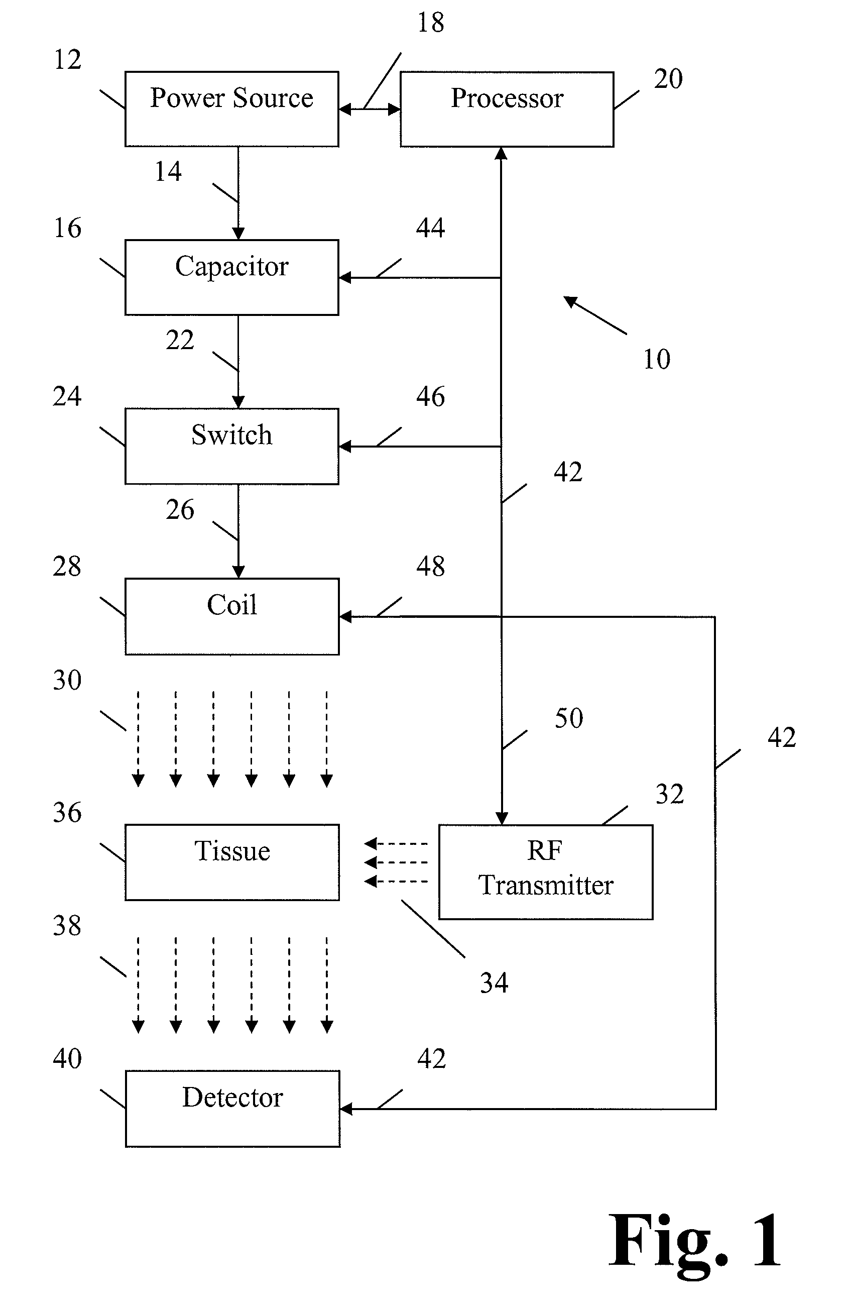
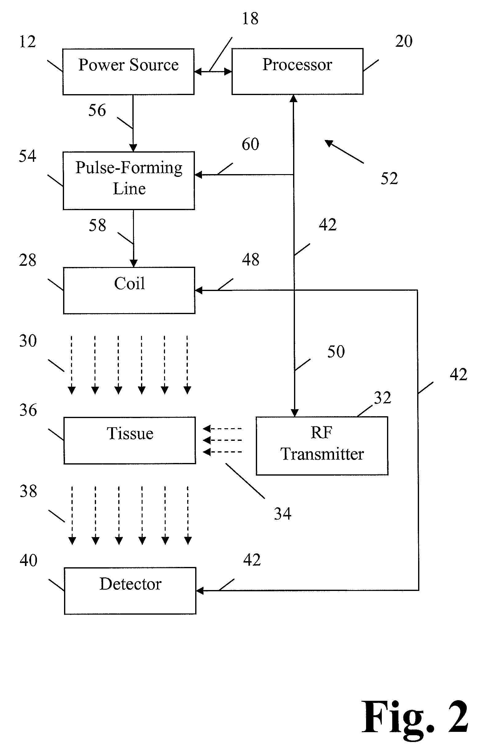
[0053]As a general rule, an MRI device includes a magnetic field generator, typically a magnetic coil and a radio frequency (“RF”) generator or transmitter. The magnetic coil generates a time-varying magnetic field and the RF generator emits radio waves. The MRI device typically also applies a static magnetic fie...


PUM


Abstract

A magnetic field generator includes a power source and a coil connected to the power source to generate a time-varying magnetic field. Energy is applied to the coil so that the coil generates a time-varying magnetic field gradient with a magnitude of at least 1 milliTesla per meter and a rise-time of less than 10 microseconds. One or more of a capacitor, a multi-stage high-voltage switch, and / or a pulse-forming network may assist with the generation of the magnetic field gradient.

Description

CROSS-REFERENCE TO RELATED APPLICATION(S)[0001]This is a United States Non-Provisional Patent Application that relies for priority on U.S. Provisional Patent Application Ser. No. 61 / 074,397, filed on Jun. 20, 2008, the contents of which are incorporated herein by reference.GOVERNMENT LICENSE RIGHTS[0002]The U.S. Government has a paid-up license in this invention and the right in limited circumstances to require the patent owner to license others on reasonable terms as provided for by the terms of Contract No. 2R42HL086294 awarded by the “National Lung and Blood Institute”.FIELD OF THE INVENTION[0003]The present invention concerns an apparatus and a method for decreasing the bio-effects of magnetic field gradients on tissue(s). More specifically, the present invention concerns an apparatus and a method to decrease bio-effects on neurological tissue from magnetic field gradients, such as those experienced during Magnetic Resonance Imaging (“MRI”).DESCRIPTION OF RELATED ART[0004]As sho...

Claims


Application Information

Patent Timeline
Patent Type & Authority Patents(United States)
IPC IPC(8): G01V3/00
CPCG01R33/3852G01R33/288
Inventor WEINBERG, IRVING
Owner WEINBERG MEDICAL PHYSICS
Learn More