Holographic image projection systems

a projection system and image technology, applied in the field of holographic image projection systems, can solve the problems of keystone distortion in the field of displayed images, and achieve the effect of facilitating extreme distortion and miniaturisation of the projector

Inactive Publication Date: 2012-04-10
PROMETHEAN
View PDF35 Cites 12 Cited by
  • Summary
  • Abstract
  • Description
  • Claims
  • Application Information

AI Technical Summary

Benefits of technology

[0008]In embodiments of the system, because diffraction is employed light from the entire illuminated area of the hologram can be directed into the distorted target image field. Moreover, the displayed image is substantially focus-free; that is the focus of the displayed image does not substantially depend upon the distance from the holographic image projection system to the display surface. A demagnifying optical system may be employed to increase the divergence of the modulated light to form the displayed image, thus allowing an image of a useful size to be displayed at a practical distance.
[0015]The holographic techniques employed in preferred embodiments of the projector facilitate miniaturisation of the projector. These techniques also facilitate handling of extreme distortion caused by projection onto a surface on which the projector is placed, this extreme distortion resulting from the geometry illustrated in later FIG. 1c in combination with the small size of the projector. Thus in some preferred embodiments the surface onto which the image is projected is no more than 1 m, 0.5 m, 0.3 m, 0.2 m, 0.15 m, or 0.1 m away from the output of the projection optics 102. Similarly in embodiments the distance from the output of the projection optics to the furthest edge of the displayed image (d2 in FIG. 1c later) is substantially greater than the distance from the output of the projection optics to the nearest edge of the displayed image (d1 in FIG. 1c), for example 50%, 100%, 150%, 200% or 250% greater. Depending upon the geometry the acute projection angle (angle Θ in FIG. 1c) may be less than 70°, 65°, 60°, 55°, 50°, or even 45°.

Problems solved by technology

The field of the displayed image suffers from keystone distortion, the trapezoidal distortion of a nominally rectangular input image field caused by projection onto a surface at an angle which is not perpendicular to the axis of the output optics.

Method used


Image

  • Holographic image projection systems
  • Holographic image projection systems
  • Holographic image projection systems

Examples


Embodiment Construction

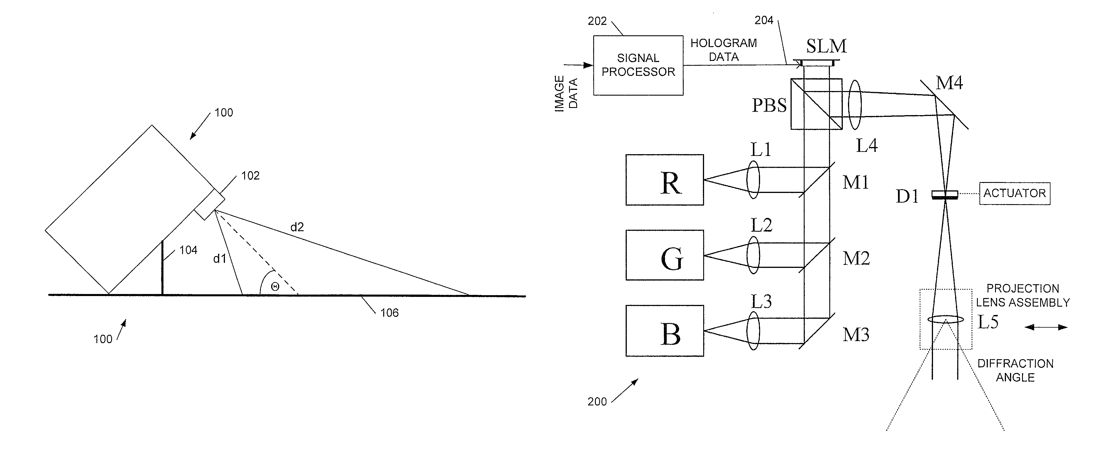
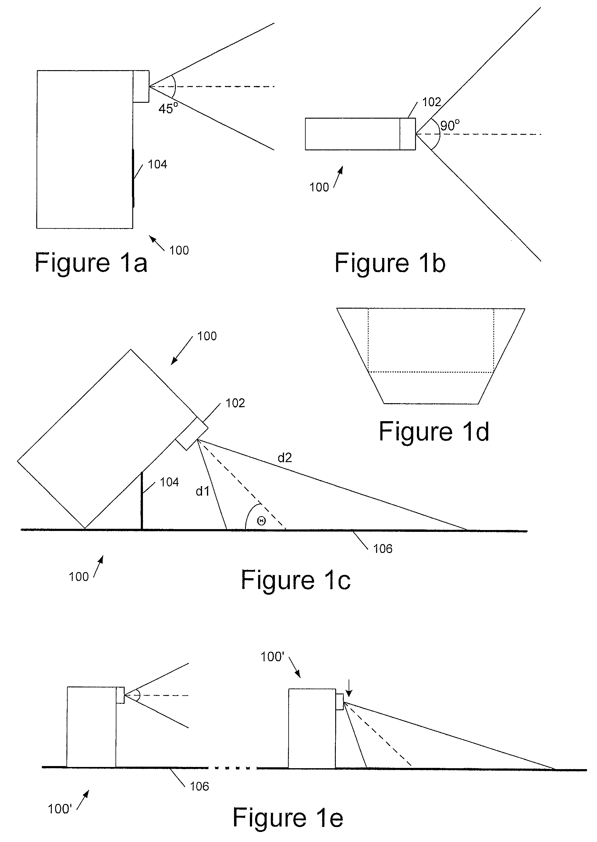
[0033]Referring to FIG. 1a, this shows a side view of an embodiment of a holographic image projection device 100 having 2 configurations, the first configuration in which the device projects forwards, and a second configuration (shown in FIG. 1c) in which the device projects outwards and downwards onto a surface 106 such as a table-top. The device includes an output lens 102 and a foldable stand, for example a bipod stand 104 to support the device in its table-down configuration. In some preferred embodiments the foldable support 104 or some similar mechanism supports the device at a known angle to the surface 106 in its table-down configuration, which has the advantage that the degree of keystone distortion is also known and can therefore automatically be compensated for. Further, in embodiments because the table-down configuration is a pre-determined configuration a calibration procedure can be used to determine not only the general keystone distortion but also other aberrations w...


PUM


Abstract

A holographic image projection system for projecting an image at an acute angle onto a surface includes: a spatial light modulator (SLM) to display a hologram; an illumination system to illuminate the displayed hologram; projection optics to project light from the illuminated displayed hologram onto the surface at an acute angle form the image; and a processor having an input to receive input image data for display and an output to provide hologram data for the SLM, wherein the processor is configured to: input image data and convert this to target image data; generate from the target image data hologram data for display as a hologram on the SLM to reproduce a target image; and wherein the target image is distorted to compensate for the projection of the hologram at an acute angle to form the image.

Description

CLAIM OF PRIORITY[0001]This application claims priority under 35 U.S.C. §119 to United Kingdom Application No. 0822336.4, filed Dec. 8, 2008, which is incorporated in its entirety by reference herein.BACKGROUND OF THE INVENTION[0002]1. Field of the Invention[0003]This invention relates to holographic image projection systems, more particularly to systems which are able to project down on to a table at an acute angle, preferably as well as projecting forwards. The invention also provides related methods and corresponding processor control code.[0004]2. Description of the Related Art[0005]We have previously described techniques for displaying an image holographically—see, for example, WO 2005 / 059660 (Noise Suppression Using One Step Phase Retrieval), WO 2006 / 134398 (Hardware for OSPR), WO 2007 / 031797 (Adaptive Noise Cancellation Techniques), WO 2007 / 110668 (Lens Encoding), and WO 2007 / 141567 (Colour Image Display). These are all hereby incorporated by reference in their entirety.[0006...

Claims


Application Information

Patent Timeline
Patent Type & Authority Patents(United States)
IPC IPC(8): G03H1/08G03H1/12
CPCG03H1/22G03H1/2205G03H2001/2215G03H2001/2218G03H1/2249G03H2210/20G06T5/006H04N5/7416
Inventor CABLE, ADRIAN JAMESROUTLEY, PAULLAWRENCE, NIC
Owner PROMETHEAN
Why Eureka
Try Eureka