
Potential control for high-voltage devices

a high-voltage device and potential control technology, applied in the direction of transmission, electrical equipment, line-transmission, etc., can solve the problems of increasing the load on the switching elements used, and achieve the effect of improving fault resilience and operation

Active Publication Date: 2012-04-10
SIEMENS HEALTHCARE GMBH
View PDF10 Cites 3 Cited by
  • Summary
  • Abstract
  • Description
  • Claims
  • Application Information

AI Technical Summary

Benefits of technology

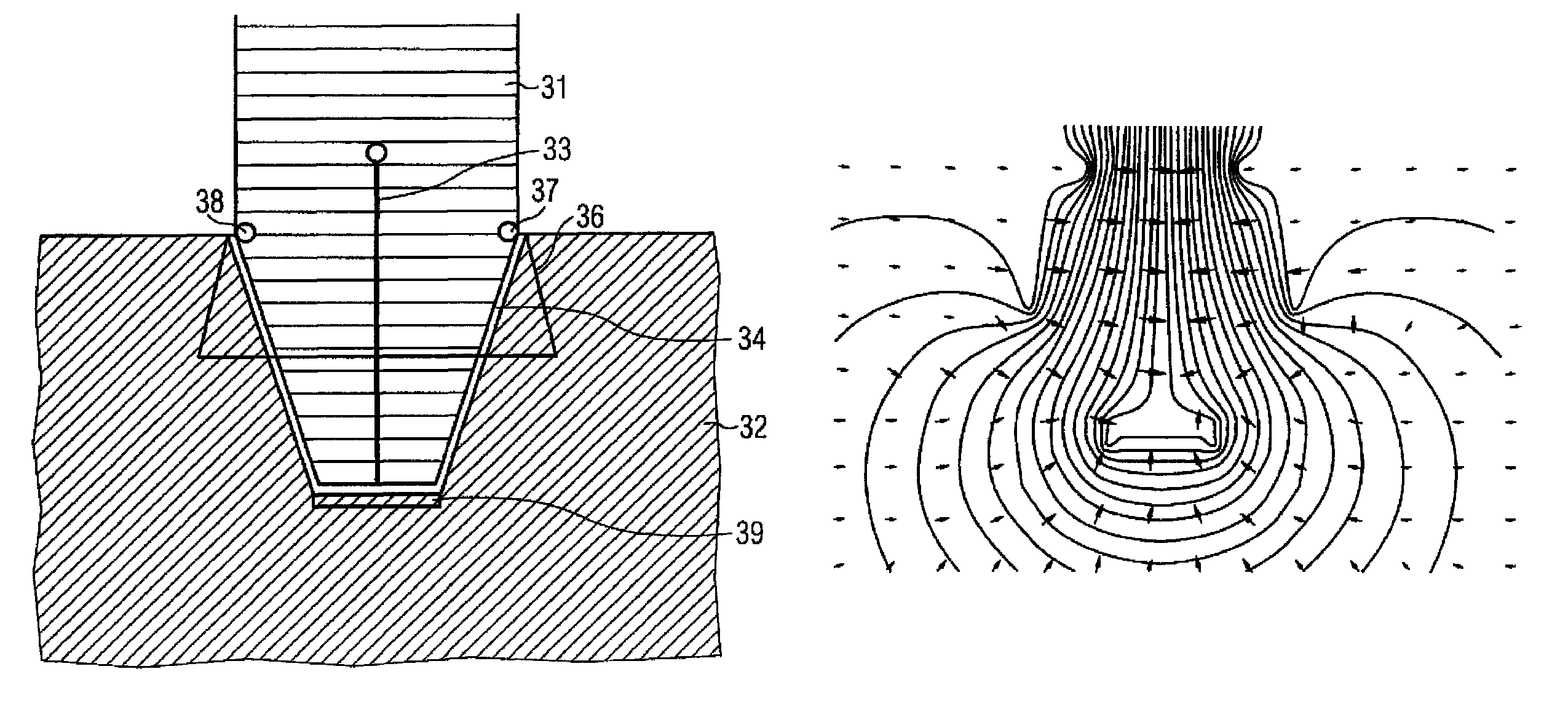
The present invention improves the fault resilience and operation of high-voltage systems by controlling changes to the electric field or potential distribution. This is achieved by adding additional conductive elements that have a defined potential value and can effect a more favorable field distribution. The additional elements can be placed in proximity to device elements that are exposed to high voltages during operation. The position, shape, and potential value of the additional elements are determined in such a way that the electric field strength is reduced in proximity to the device element. This results in a more uniform distribution of the electric field and reduces the maximum loadings on switching elements or carriers. The invention also includes a high-voltage connector system that generates a uniform field distribution in the vicinity of the connector system by the position, shape, and potential value of the device element.

Problems solved by technology

The use of high voltage leads to an increased load being imposed on the switching elements used.

Method used


Image

  • Potential control for high-voltage devices
  • Potential control for high-voltage devices
  • Potential control for high-voltage devices

Examples


Embodiment Construction

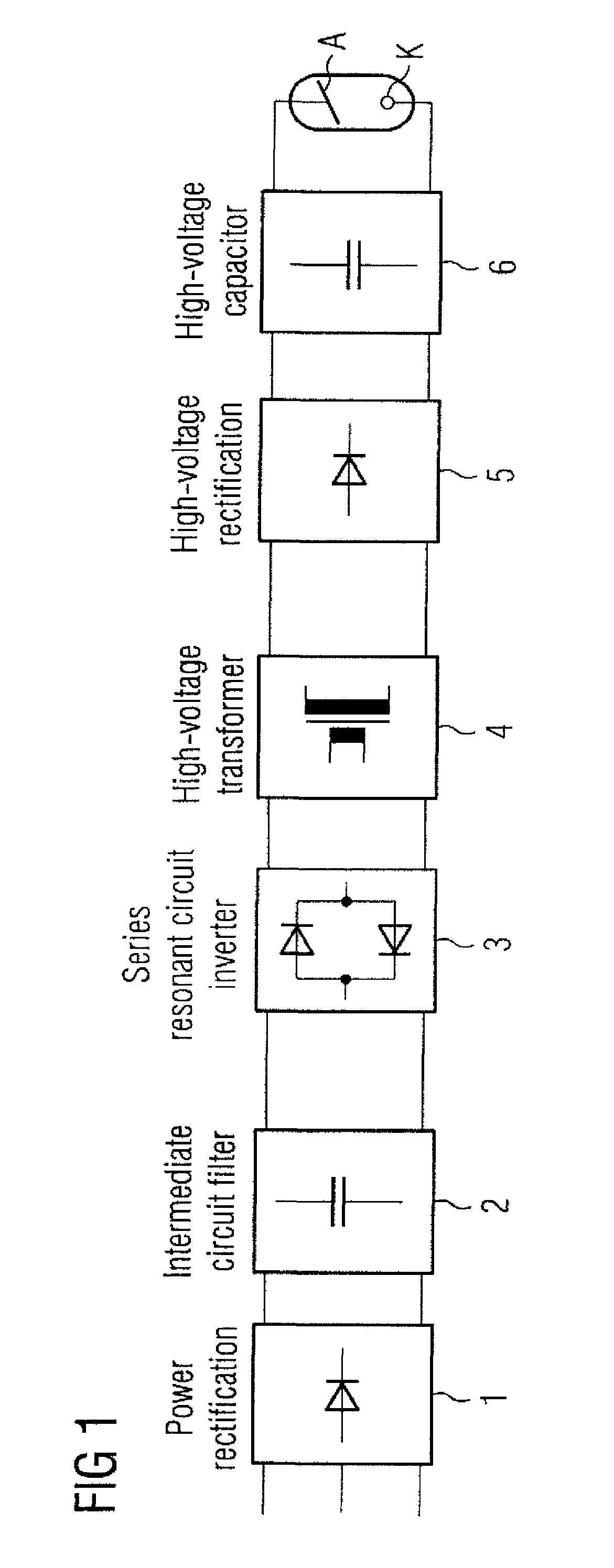
[0021]FIG. 1 shows a schematic circuit diagram of an X-ray generator implemented in inverter technology. The voltage applied to the X-ray tube 7 between anode A and cathode K is a direct-current voltage. The direct-current voltage may be obtained by a power rectifier 1 and an intermediate circuit filter 2. The direct-current voltage may be converted into an alternating-current voltage by a series resonant circuit inverter 3. The alternating-current voltage may be transformed by a high-voltage transformer 4 into a high voltage, which is converted into a direct-current voltage, for the X-ray tube 7 by a high-voltage rectifier 5 and filtered by a high-voltage capacitor 6.

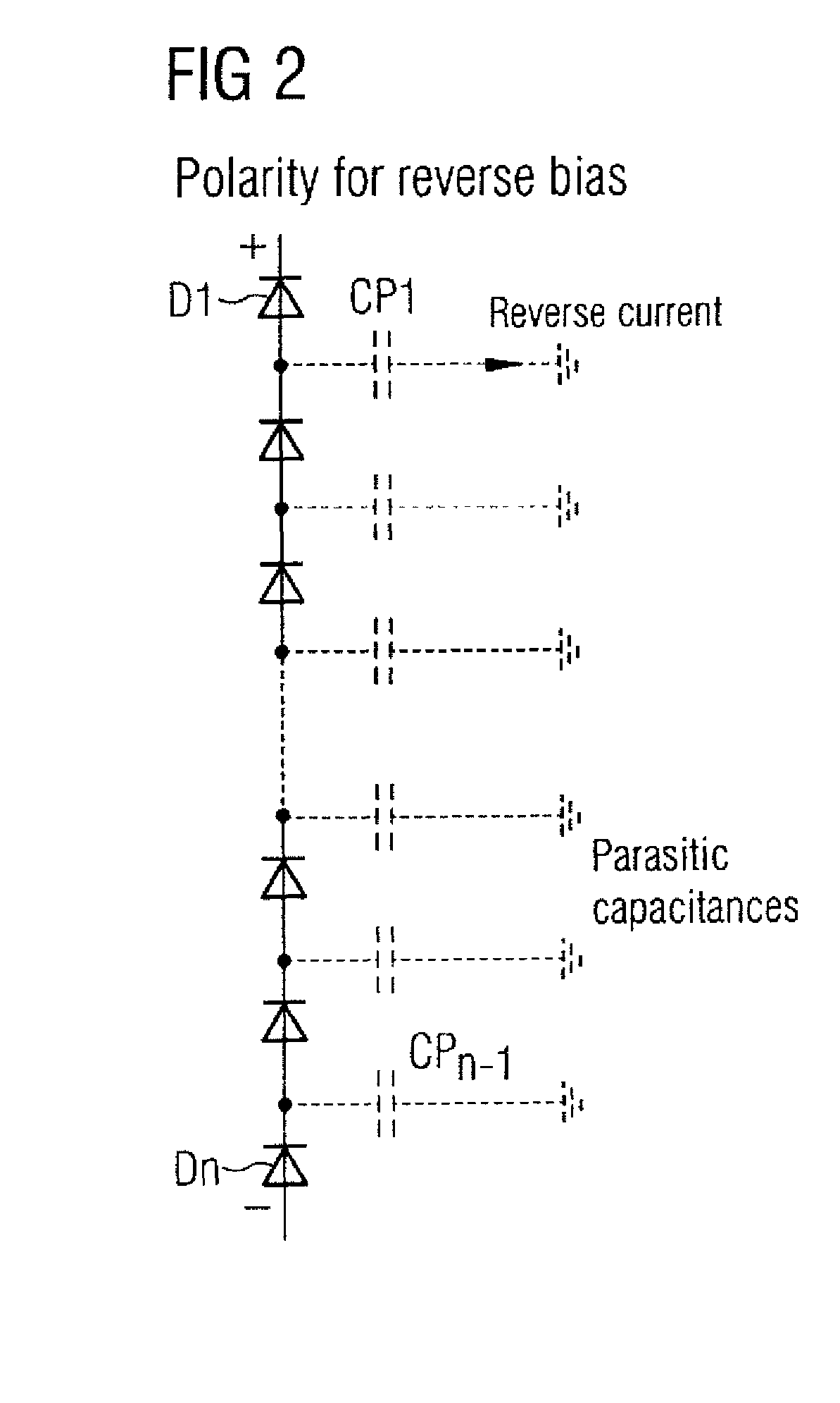
[0022]The high voltage at the X-ray tube 7 may be 75 kV and more relative to ground or reference potential. As shown in FIG. 2, the high-voltage rectifier 6 is assembled from an array of commercially available high-voltage diodes connected in series. FIG. 2 illustrates a diode chain (diodes D1 . . . Dn) of a high-volta...


PUM


Abstract

The present embodiments related to a device having a device element to which a high voltage can be applied. The device is provided with at least one additional conducting element which is disposed, embodied and connected in such a way that the element is assigned a defined potential value and a change to the electric field generated by the high voltage in the sense of a more favorable field distribution is effected by means of position, shape and potential value. According to the invention, maximum loads on switching elements are avoided and undesirable phenomena such as voltage breakdowns or flow voltages are counteracted as a result of the more favorable field distribution.

Description

[0001]This application claims the benefit of DE 10 2007 032 808.9 filed Jul. 13, 2007, which is hereby incorporated by reference.BACKGROUND[0002]The present embodiments relate a device element to which a reference voltage is applied.[0003]High voltages (e.g., voltages that typically lie in the 50-150 kV range) are used for power transmission and for producing a variety of technical and physical effects, such as, for generating X-radiation, electric arcs, in cathode ray tubes, ignition coils, or for fluorescent lighting. A precisely adjusted high voltage (e.g., in the form of direct-current voltage) is required for generating electric fields, e.g. in order to accelerate or deflect electrons or other elementary particles. Precision high-voltage power supplies are used for generating the high voltage. DE 10227841 discloses a high-voltage power supply that generates a direct-current voltage for an X-ray tube. An intermediate circuit direct-current voltage is obtained from an input volta...

Claims


Application Information

Patent Timeline
Patent Type & Authority Patents(United States)
IPC IPC(8): H05G1/12
CPCH05G1/10
Inventor BEYERLEIN, WALTEREICHHORN, RICHARDKUHNEL, WERNERMISSEL, SABINE
Owner SIEMENS HEALTHCARE GMBH
Learn More