Distance estimation apparatus, distance estimation method, storage medium storing program, integrated circuit, and camera

a distance estimation and distance estimation technology, applied in the field of distance estimation apparatus, distance estimation method, storage medium storing program, integrated circuit, etc., can solve the problems of inability to obtain a uniquely determined distance calculation, unsuitable triangulation for applications, and a relatively long time-consuming and laborious to obtain 3d information of the entire target space. , to achieve the effect of the same advantageous

Active Publication Date: 2012-04-17
PANASONIC INTELLECTUAL PROPERTY CORP OF AMERICA
View PDF8 Cites 24 Cited by
  • Summary
  • Abstract
  • Description
  • Claims
  • Application Information

AI Technical Summary

Benefits of technology

[0070]The distance estimation method has the same advantageous effects as the distance estimation apparatus of the first aspect of the present invention.
[0071]A ninth aspect of the present invention provides a distance estimation method for illuminating an object with light having a modulated light intensity and estimating a distance to an object using reflected light from the object. The method is used by a distance estimation apparatus including a light source operable to emit light whose light intensity can be modulated, a light receiving optical system operable to focus light from the object, a color separation unit operable to separate light received by the light receiving optical system into a first light component and a second light component based on a frequency of the light, a light receiving unit operable to convert the second light component separated by the color separation unit to obtain charge, a charge accumulation unit operable to accumulate the charge obtained by the light receiving unit and obtain a charge signal, and an imaging unit operable to convert the second light component separated by the color separation unit to an image generation charge signal. The distance estimation method includes a light source control process, a signal processing process, a distance image generation process, a distance image storage process, a high resolution image generation process, a high resolution image storage process, a motion vector detection process, and a distance image correction process. In the light source control process, the light sources is controlled. In the signal processing process, distance information is calculated based on the charge signal. In the distance image generation process, a distance image having a first number of pixels is generated based on the distance information. In the distance image storage process, the distance image is stored. In the high resolution image generation process, a high resolution image having pixels more than the first number of pixels is generated based on the image generation charge signal obtained by the imaging unit. In the high resolution image storage process, the high resolution image is stored. In the motion vector detection process, a motion vector is detected by comparing a high resolution image Img_color(t) that is obtained at a predetermined unit timing t in the high resolution image generation process and a high resolution image Img_color(t−α) that is obtained at a timing (t−α) preceding the predetermined unit timing t and stored in the high resolution image storage process. In the distance image correction process, distance information of a target pixel of the distance image is corrected based on a distance image Img_distance(t) that is obtained at the predetermined unit timing t in the distance image generation process, a distance image Img_distance(t−α) that is obtained at the timing (t−α) preceding the predetermined unit timing t and stored in the distance image storage process, and a motion vector that is detected in the motion vector detection process.
[0072]The distance estimation method has the same advantageous effects as the distance estimation apparatus of the fourth aspect of the present invention.
[0073]A tenth aspect of the present invention provides a distance estimation method for illuminating an object with light having a modulated light intensity and estimating a distance to an object using reflected light from the object. The method is used by a distance estimation apparatus including a light source operable to emit light whose light intensity can be modulated, a light receiving optical system operable to focus light from the object, a light receiving unit operable to convert the light received by the light receiving optical system to obtain charge, and a charge accumulation unit operable to accumulate the charge obtained by the light receiving unit and obtain a charge signal. The method includes a light source control process, a signal processing process, a distance image generation unit, a distance reliability calculation process, and a distance image correction process.
[0074]In the light source control process, the light source is controlled. In the signal processing process, distance information is calculated based on the charge signal. In the distance image generation unit, a distance image is generated based on the distance information. In the distance reliability calculation process, a reliability of a pixel of the distance image is calculated based on at least one of the distance information and the charge signal. In the distance image correction process, distance information of the pixel of the distance image is corrected based on the reliability calculated in the distance reliability calculation process.
[0075]The distance estimation method has the same advantageous effects as the distance estimation apparatus of the fifth aspect of the present invention.

Problems solved by technology

The measurement using triangulation requires a relatively long time to obtain 3D information of the entire target space.
Thus, triangulation is considered unsuitable for applications that would require, for example, tracking of a moving object.
However, when the distance to the measurement-target object is greater than or equal to the value of the wavelength corresponding to the cycle of the intensity modulation of the measurement light beam, the phase TOF method in principle would fail to obtain a uniquely determined distance calculation result (in other words, this method would fail to determine the distance to the measurement-target object).
The pulse TOF method consequently requires a long time to obtain a distance image.

Method used


Image

  • Distance estimation apparatus, distance estimation method, storage medium storing program, integrated circuit, and camera
  • Distance estimation apparatus, distance estimation method, storage medium storing program, integrated circuit, and camera
  • Distance estimation apparatus, distance estimation method, storage medium storing program, integrated circuit, and camera

Examples


first embodiment

[0146]The first embodiment of the present invention will now be described with reference to FIGS. 1 to 5.

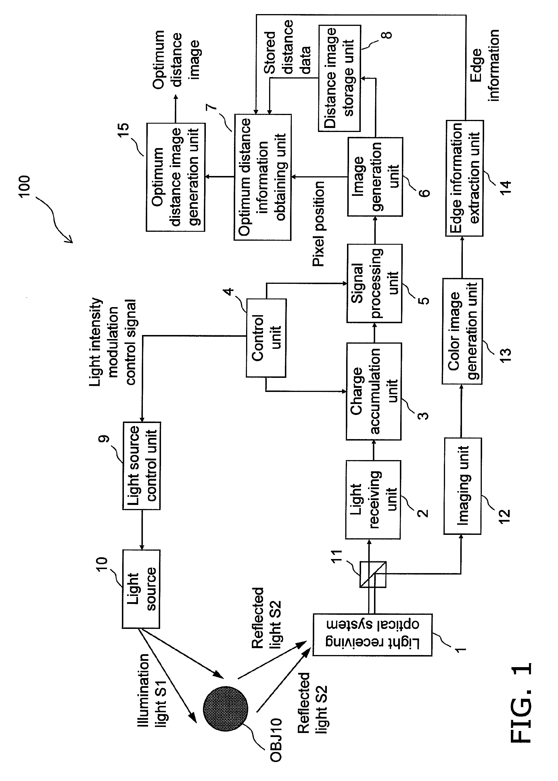
[0147]FIG. 1 is a schematic block diagram of a distance estimation apparatus 100 according to the first embodiment.

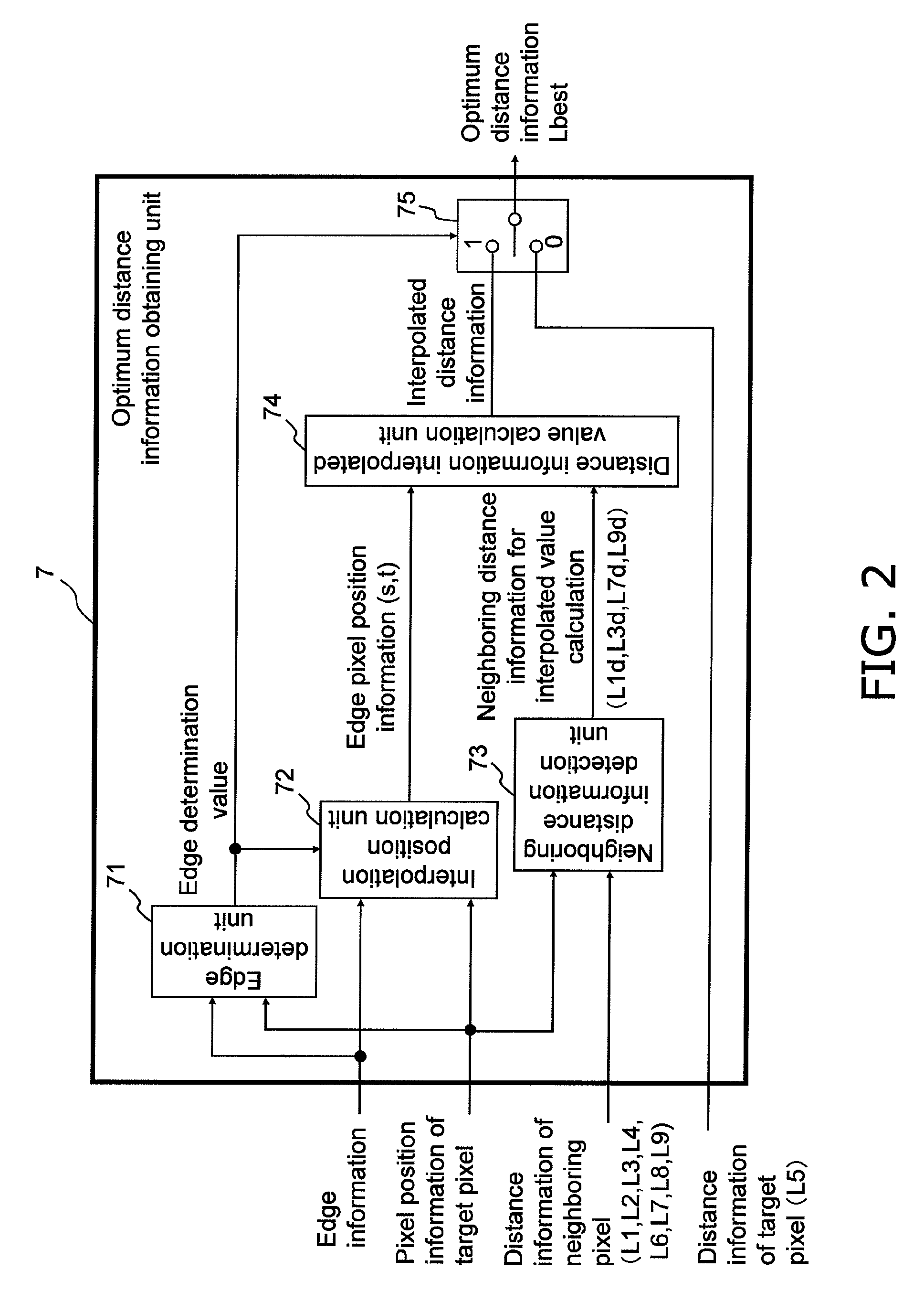
[0148]FIG. 2 is a schematic block diagram of an optimum distance information obtaining unit 7 included in the distance estimation apparatus 100 of the first embodiment.

[0149]FIGS. 3A and 3B schematically show an overview of image interpolation performed with a distance estimation method according to the first embodiment.

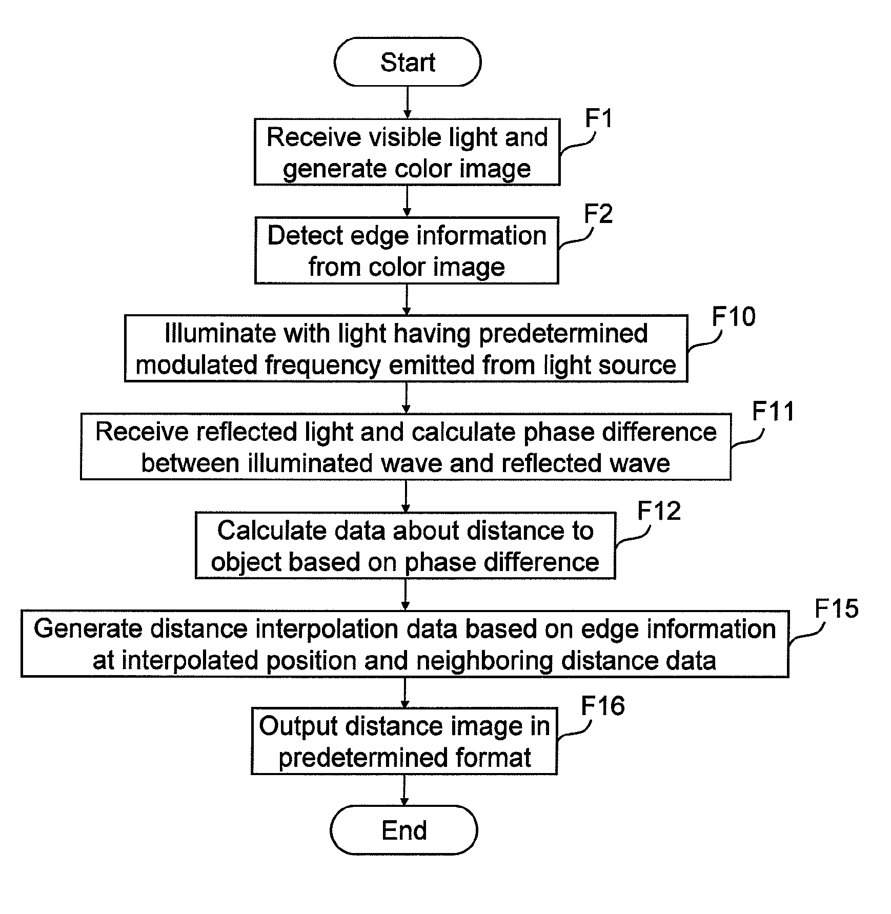
[0150]FIG. 4 is a flowchart showing the processing performed with the distance estimation method of the first embodiment.

[0151]FIG. 5A schematically shows an overview of second image interpolation (first modification) and FIG. 5B schematically shows an overview of third image interpolation (second modification) performed with the distance estimation method of the first embodiment.

[0152]The distance estimation apparatus and the distance estimation meth...

first modification

[0243]Alternatively, the distance estimation apparatus 100 may perform distance information interpolation with a modified method described below instead of the above method described with reference to FIGS. 3A and 3B. The first modified method will now be described with reference to FIG. 5A. In FIG. 5A, the processing part that is the same as the processing described with reference to FIGS. 3A and 3B is shown in the same manner as in FIGS. 3A and 3B and will not be described.

[0244]As shown in FIG. 5A, the distance estimation apparatus 100 first determines whether a block (image area) in the color image corresponding to the target pixel of the distance pixel (target pixel of the light receiving element for distance estimation) includes edge information. (B) When the target pixel of the distance image includes no edge information, the distance estimation apparatus 100 determines that the target pixel belongs to a flat area, and outputs distance information of the target pixel of the d...

second modification

[0251]Alternatively, the distance estimation apparatus 100 may perform distance information interpolation using another modified method described below instead of the method described with reference to FIGS. 3A and 3B. The second modified method will now be described with reference to FIG. 5B. In FIG. 5B, the processing part that is the same as the processing described with reference to FIGS. 3A and 3B is shown in the same manner as in FIGS. 3A and 3B and will not be described.

[0252]As shown in FIG. 5B, the distance estimation apparatus 100 first determines whether a block (image area) in the color image corresponding to the target pixel of the distance pixel (target pixel of the light receiving element for distance estimation) includes edge information.

[0253](B) When the target pixel of the distance image includes no edge information, the distance estimation apparatus 100 determines that the target pixel belongs to a flat area, and outputs distance information of the target pixel o...


PUM


Abstract

Attempts to achieve a higher resolution and a higher frame rate of a distance image when a distance to an object within a target space is estimated using the TOF method would cause CCD saturation due to shot noise or environment light, and lower distance precision. A distance estimation apparatus illuminates an object with illumination light for distance estimation emitted from a light source that can emit light (electromagnetic wave) having a predetermined illumination frequency, receives reflected light of the illumination light, obtains information about the distance from the apparatus to the object, generates distance image data based on the distance information, extracts edge information of a color image formed using a visible light component obtained in synchronization with the reflected light, and corrects distance information of a target part of the distance image using distance information of a neighboring part of the target part based on the edge information.

Description

[0001]This application claims priority to Japanese Patent Application No 2008-211055 filed on Aug. 19, 2008, the entire disclosure of which is hereby incorporated herein by reference.BACKGROUND OF THE INVENTION[0002]1. Field of the Invention[0003]The present invention relates to an apparatus and a method that enhance depth feel and stereoscopic effect of an image formed by an imaging apparatus, such as a movie camera or a digital still camera (DSC), by capturing an image of a target space and estimating a distance to an object within the target space.[0004]2. Description of the Related Art[0005]Three-dimensional space measuring techniques have potential applications in many fields. To put the 3D space measuring techniques into practical use, a variety of methods have been used. Typical methods include light sectioning of laser slit light using scanning, triangulation such as stereo triangulation, and a TOF method for determining a distance by illuminating a measurement-target object...

Claims


Application Information

Patent Timeline
Patent Type & Authority Patents(United States)
IPC IPC(8): H04N5/232G01S17/894
CPCG01S17/36G01S17/89G06T7/0067H04N2213/006G06T2207/10028G06T7/564G01S17/894
Inventor WATANABE, TATSUMIKUWAHARA, YASUHIROITO, TAKESHITOJI, BUMPEISATO, DAISUKEKIUCHI, SHINYAOWAKI, YOSHIAKI
Owner PANASONIC INTELLECTUAL PROPERTY CORP OF AMERICA
Why Eureka
Try Eureka